Heat dissipation-facilitated box type substation

A technology of box-type substations and cooling vents is applied in the details of substation/switch layout, cooling/ventilation of substations/switchgears, electrical components, etc. problems, to ensure safe and normal operation and ensure the effect of heat dissipation

Inactive Publication Date: 2018-11-16
安徽和光电气设备有限公司
View PDF6 Cites 9 Cited by
  • Summary
  • Abstract
  • Description
  • Claims
  • Application Information

AI Technical Summary

Problems solved by technology

[0002] In the field of electric power foundation, box-type substation is a common equipment. Most modern box-type substations are composed of a rectangular metal box. Box-type substations are usually used outdoors. Because the outdoor environment is generally worse than indoors, the box-type substation The interior of the box-type substation is generally equipped with continuous cooperating power equipment, and will generate large currents. Therefore, the internal heat generation of the box-type substation is generally relatively large. If the temperature is too high, it is very easy to damage the power equipment installed inside the box-type substation. Traditional The heat dissipation of the box-type substation is very slow, which is not conducive to the safe operation of power supply equipment

Method used


Image

  • Heat dissipation-facilitated box type substation
  • Heat dissipation-facilitated box type substation
  • Heat dissipation-facilitated box type substation

Examples


Embodiment Construction

[0026] The following will clearly and completely describe the technical solutions in the embodiments of the present invention with reference to the accompanying drawings in the embodiments of the present invention. Obviously, the described embodiments are only some, not all, embodiments of the present invention. All other embodiments obtained by persons of ordinary skill in the art based on the embodiments of the present invention belong to the protection scope of the present invention.

[0027] According to an embodiment of the present invention, a box-type substation that facilitates heat dissipation is provided.

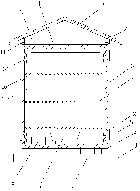
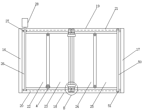
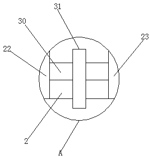
[0028] like Figure 1-5 As shown, the box-type substation convenient for heat dissipation according to the embodiment of the present invention includes an installation base 1, a buffer layer 2 is arranged on the top of the installation base 1, and a box-type substation body 3 is arranged on the top of the buffer layer 2. The box The top of the substation body 3 i...


PUM


Abstract

The invention discloses a heat dissipation-facilitated box type substation. The heat dissipation-facilitated box type substation comprises a mounting base; the top of the mounting base is provided with a buffer layer; the top of the buffer layer is provided with a box type substation body; the top of the box type substation body is provided with supporting columns; the tops of the supporting columns are provided with a rain blocking cover; a plurality of buffer mechanisms are uniformly arranged in the buffer layer; the bottom end of the interior of the box type substation body is provided witha heat dissipation fan and a controller located to one side of the heat dissipation fan; a plurality of partition plates are sequentially arranged in the box type substation body; a plurality of heatdissipation holes are evenly formed in the partition plates; the top end of the box type substation body is provided with a movable mechanism disposed at the inner sides of the supporting columns; air inlets are formed in the bottom end of the side wall of the box type substation body; heat dissipation openings A are formed in the top end of the side wall of the box type substation body; and heatdissipation openings B are formed in the supporting columns. The heat dissipation effect of the box type substation and the safe and normal operation of power equipment can be ensured.

Description

technical field [0001] The invention relates to the technical field of electric power equipment, in particular to a box-type substation which is convenient for heat dissipation. Background technique [0002] In the field of electric power foundation, box-type substation is a common equipment. Most modern box-type substations are composed of a rectangular metal box. Box-type substations are usually used outdoors. Because the outdoor environment is generally worse than indoors, the box-type substation The interior of the box-type substation is generally equipped with continuous cooperating power equipment, and will generate large currents. Therefore, the internal heat generation of the box-type substation is generally relatively large. If the temperature is too high, it is very easy to damage the power equipment installed inside the box-type substation. Traditional The box-type substation dissipates heat very slowly, which is not conducive to the safe operation of power supp...

Claims


Application Information

Patent Timeline
Patent Type & Authority Applications(China)
IPC IPC(8): H02B1/46H02B1/56
CPCH02B1/46H02B1/565
Inventor 孙弘
Owner 安徽和光电气设备有限公司
Why Eureka
Try Eureka