InstaLLing and fixing structure of rear combined Lamp

A fixed structure, rear combination lamp technology, applied in the direction of signal devices, transportation and packaging, optical signals, etc., can solve the problems of gap and surface difference, and achieve the effect of convenient installation

Inactive Publication Date: 2018-11-23
ANHUI JIANGHUAI AUTOMOBILE GRP CORP LTD
View PDF5 Cites 2 Cited by
  • Summary
  • Abstract
  • Description
  • Claims
  • Application Information

AI Technical Summary

Problems solved by technology

[0003] The purpose of the present invention is to provide a rear combination lamp installation and fixing structure to solve the technical problems in the prior art, which can make the gap between the B lamp and the trunk lid sheet metal easy to control, and the installation is convenient and simple

Method used


Image

  • InstaLLing and fixing structure of rear combined Lamp
  • InstaLLing and fixing structure of rear combined Lamp
  • InstaLLing and fixing structure of rear combined Lamp

Examples


Embodiment Construction

[0020] The embodiments described below by referring to the figures are exemplary only for explaining the present invention and should not be construed as limiting the present invention.

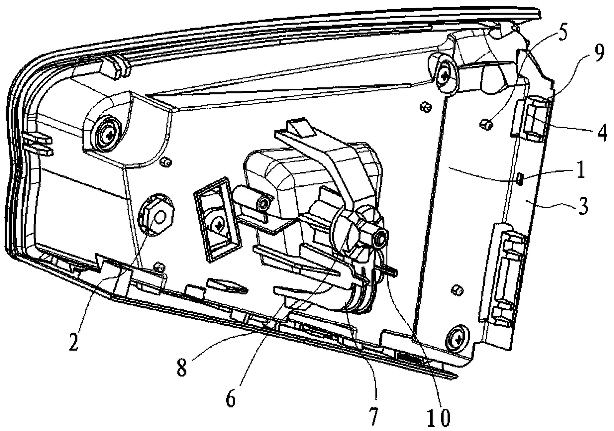
[0021] Such as image 3 As shown, the embodiment of the present invention provides a rear combination lamp installation and fixing structure, including a lamp body 1 and a first fixing assembly, a second fixing assembly and an embedded nut 2 arranged on the back of the lamp body 1. The first fixing component and the embedded nut 2 are arranged on both sides of the second fixing component, wherein:

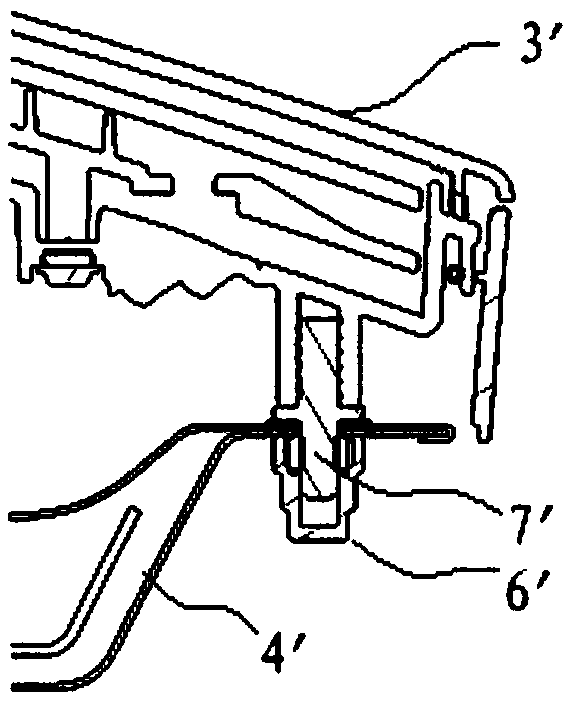
[0022] By setting embedded nuts 2 on the lamp body 1, the bolts are driven into the embedded nuts 2 to fix the lamp body 1 on the trunk lid sheet metal 11, as Figure 6 As shown, the pre-embedded nut 2 is threadedly matched with the lamp body 1, and the outside of the pre-embedded nut 2 is 3mm higher than the surface of the lamp body 1, so as to facilitate tightening or loosening of the pre-embed...


PUM


Abstract

The invention discLoses an instaLLing and fixing structure of a rear combined Lamp. The instaLLing and fixing structure comprises a Lamp body, a first fixing assembLy, a second fixing assembLy and a pre-buried nut. The first fixing assembLy, the second fixing assembLy and the pre-buried nut are arranged on the back face of the Lamp body. The first fixing assembLy and the pre-buried nut are arranged on the two sides of the second fixing assembLy, wherein the first fixing assembLy comprises a verticaL pLate, a cLamping bLock and Limiting bLocks; the second fixing assembLy comprises a fixing baseand eLastic pieces arranged on the two opposite sides of the fixing base. Compared with the prior art, through the fixing mode that cLamping is performed on one side through the first fixing assembLy, cLamping is performed in the middLe through the second fixing assembLy, and screws are hit on the other side, when a Lamp B and a trunk Lid are assembLed, the cLearance pLane difference between theLamp B and a metaL pLate of the trunk Lid is easy to controL, and instaLLing is convenient and simpLe.

Description

technical field [0001] The invention relates to the technical field of automobile lamps, in particular to a mounting and fixing structure for a rear combination lamp. Background technique [0002] At present, most passenger car rear combination lights are divided into A lights and B lights, refer to figure 1 The schematic diagram of the structure of the car rear combination lamp shown and figure 2 In the structural diagram of the B lamp installation method shown in the prior art, the A lamp 1' is fixed on the automobile side wall sheet metal 2', and the B lamp 3' is fixed on the trunk lid sheet metal 4'. Usually, 4 studs 5' are pre-embedded on the B lamp 3'. The installation of the B lamp 3' is to put the 4 studs 5' on the B lamp 3' into the metal holes of the trunk lid, and then adjust the B lamp 3. ' and the trunk lid sheet metal 4' have a different clearance surface, and finally use a sleeve to fasten the nut 6' on the stud 5', so that the B lamp 3' is fixed firmly. H...

Claims


Application Information

Patent Timeline
Patent Type & Authority Applications(China)
IPC IPC(8): B60Q1/00B60Q1/30
Inventor 刘攀雷旭初翔杰黄占君王洪正
Owner ANHUI JIANGHUAI AUTOMOBILE GRP CORP LTD
Why Eureka
Try Eureka