Vehicle tail light fixing structure and vehicle tail light assembly method

A technology for automotive taillights and fixed structures, which is applied to vehicle components, signaling devices, transportation and packaging, etc. It can solve problems such as the gap between the movable taillights and the outer panel of the back door, the failure to meet the design definition requirements, and the difficulty in controlling the fixed taillights. , to achieve the effect of being conducive to lightweight design, shortening the process dimension chain, and meeting the sensory quality requirements

Active Publication Date: 2019-03-15
CHERY COMML VEHICLE ANHUI
View PDF11 Cites 2 Cited by
  • Summary
  • Abstract
  • Description
  • Claims
  • Application Information

AI Technical Summary

Problems solved by technology

At present, most of the fixed taillights are installed on the inner panel of the body side wall, and the movable taillights are installed on the inner panel of the rear door. It is difficult to control the gap between the fixed taillight and the outer panel of the side wall, and the movable taillight and the outer panel of the rear door Difference
During the assembly process of tail lights, there are often situations where the matching state is unstable, does not meet the design definition requirements, and the assembly time is too long.

Method used


Image

  • Vehicle tail light fixing structure and vehicle tail light assembly method
  • Vehicle tail light fixing structure and vehicle tail light assembly method
  • Vehicle tail light fixing structure and vehicle tail light assembly method

Examples


Embodiment Construction

[0037] In the present invention, it should be understood that the terms "length", "width", "upper", "lower", "front", "rear", "left", "right", "vertical", "horizontal" ", "Top", "Bottom", "Inner", "Outer", "Clockwise", "Counterclockwise", "Axial", "Plane Direction", "Circumferential" and other indications are based on The orientation or positional relationship shown in the drawings is only for the convenience of describing the present invention and simplifying the description, and does not indicate or imply that the referred device or element must have a specific orientation, be constructed and operated in a specific orientation, and therefore cannot be understood as Limitations on the Invention.

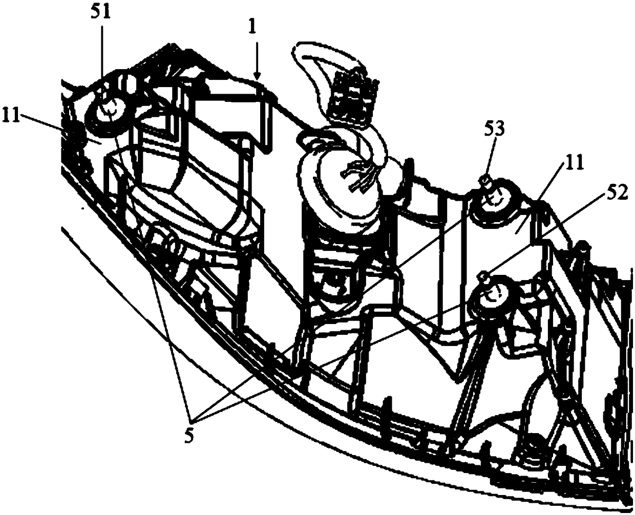
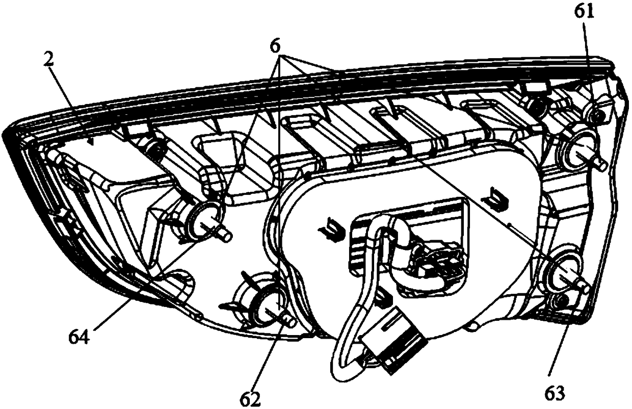
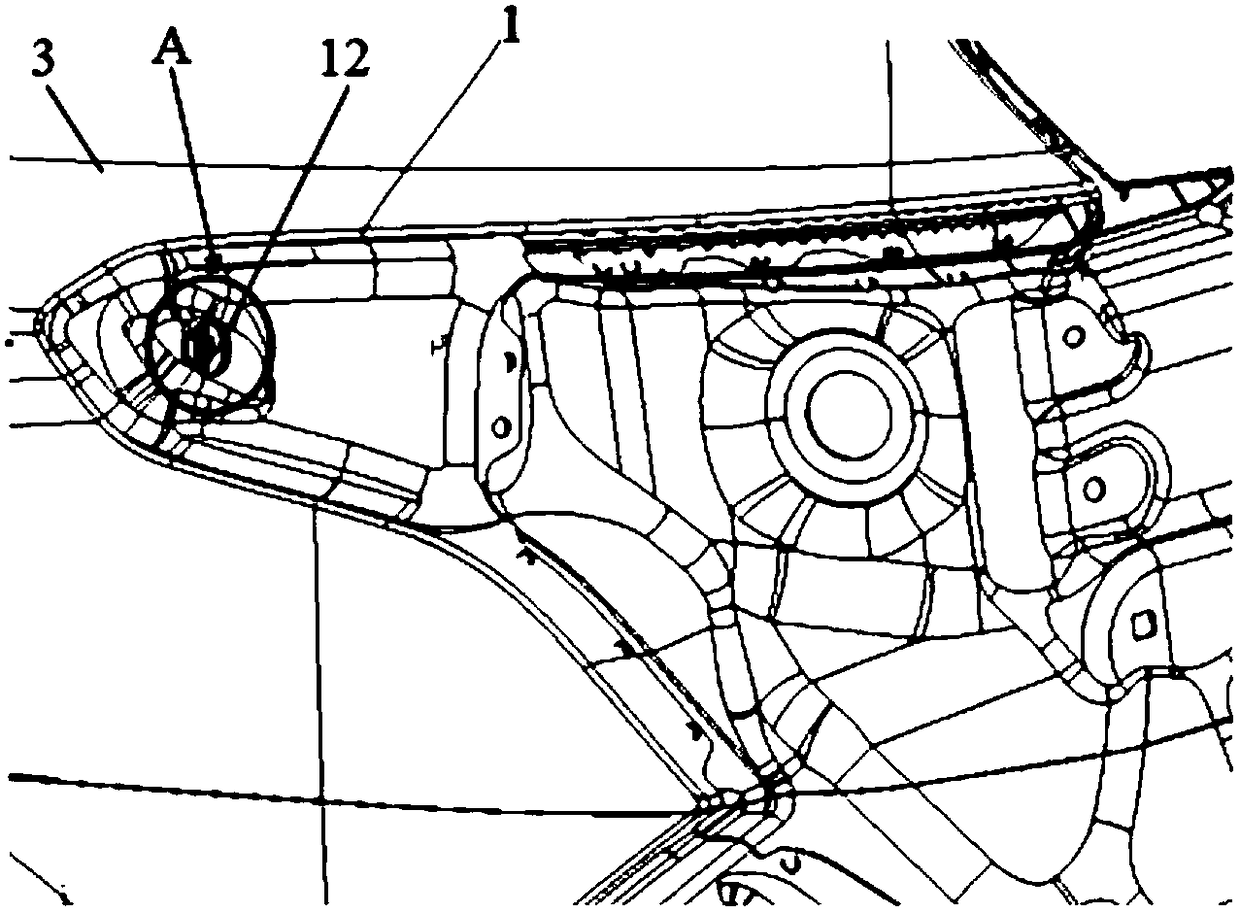
[0038] Such as Figure 1 to Figure 4 Shown, a kind of automobile taillight fixed structure, comprises fixed taillight 1, movable taillight 2, body side wall outer panel 3 and back door outer panel, fixed taillight 1 is installed on the vehicle body side wall outer panel 3, movable ...


PUM


Abstract

The invention discloses a vehicle tail light fixing structure. The vehicle tail light fixing structure comprises a fixed tail light, a movable tail light, a vehicle body side outer plate and a back door outer plate; the fixed tail light is installed on the vehicle body side outer plate, and the movable tail light is installed on the back door outer plate. In this way, the position of the fixed tail light relative to the vehicle body side outer plate and the position of the movable tail light relative to the back door outer plate are conveniently adjusted, and then the clearance plane difference between the fixed tail light and the vehicle body side outer plate and the clearance plane difference between the movable tail light and the back door outer plate are easily controlled; the fixed tail light is directly installed on the vehicle body side outer plate, the movable tail light is directly installed on the back door outer plate, the use of an inner plate is reduced, materials for thevehicle body are reduced, and lightweight design is facilitated; besides, the technological dimension chain is reduced technologically, the assembly error is reduced accordingly, and the clearance plane differences of the tail lights and the vehicle body are reduced. The invention further discloses a vehicle tail light assembly method.

Description

technical field [0001] The invention belongs to the technical field of automobile lighting systems, and in particular relates to an automobile taillight fixing structure and an automobile taillight assembly method. Background technique [0002] With the rapid development of the automobile industry and the increasingly fierce competition in the industry, consumers have higher and higher requirements for the sensory quality of automobiles, such as "refinement" has become a consideration factor for consumers when purchasing cars. As the eyes of the car, the headlights are closely related to the first impression of the whole car on the customer because of the poor coordination of the surrounding gaps and the degree of visual beauty. [0003] Existing split type automobile tail light comprises two parts of fixed tail light and movable tail light. At present, most of the fixed taillights are installed on the inner panel of the body side wall, and the movable taillights are instal...

Claims


Application Information

Patent Timeline
Patent Type & Authority Applications(China)
IPC IPC(8): B60Q1/26B60Q1/30
CPCB60Q1/2623B60Q1/30Y02T10/40
Inventor 田准陈鹏张朝林吴欢庆
Owner CHERY COMML VEHICLE ANHUI
Why Eureka
Try Eureka