
PCB cursor printing device and printing method thereof

A technology of printing device and PCB board, which is applied in the direction of exposure device of photoengraving process, printed circuit, printed circuit manufacturing, etc., can solve problems such as affecting positioning accuracy

Pending Publication Date: 2018-11-23
CAIZ OPTRONICS CORP
View PDF6 Cites 0 Cited by
  • Summary
  • Abstract
  • Description
  • Claims
  • Application Information

AI Technical Summary

Problems solved by technology

Due to the optical marking device, one on the upper and one on the bottom, during the movement, there will be displacement deviation, which directly affects the positioning accuracy

Method used


Image

  • PCB cursor printing device and printing method thereof
  • PCB cursor printing device and printing method thereof

Examples


Embodiment Construction

[0015] The structure of the present invention will be further described below in conjunction with the accompanying drawings.

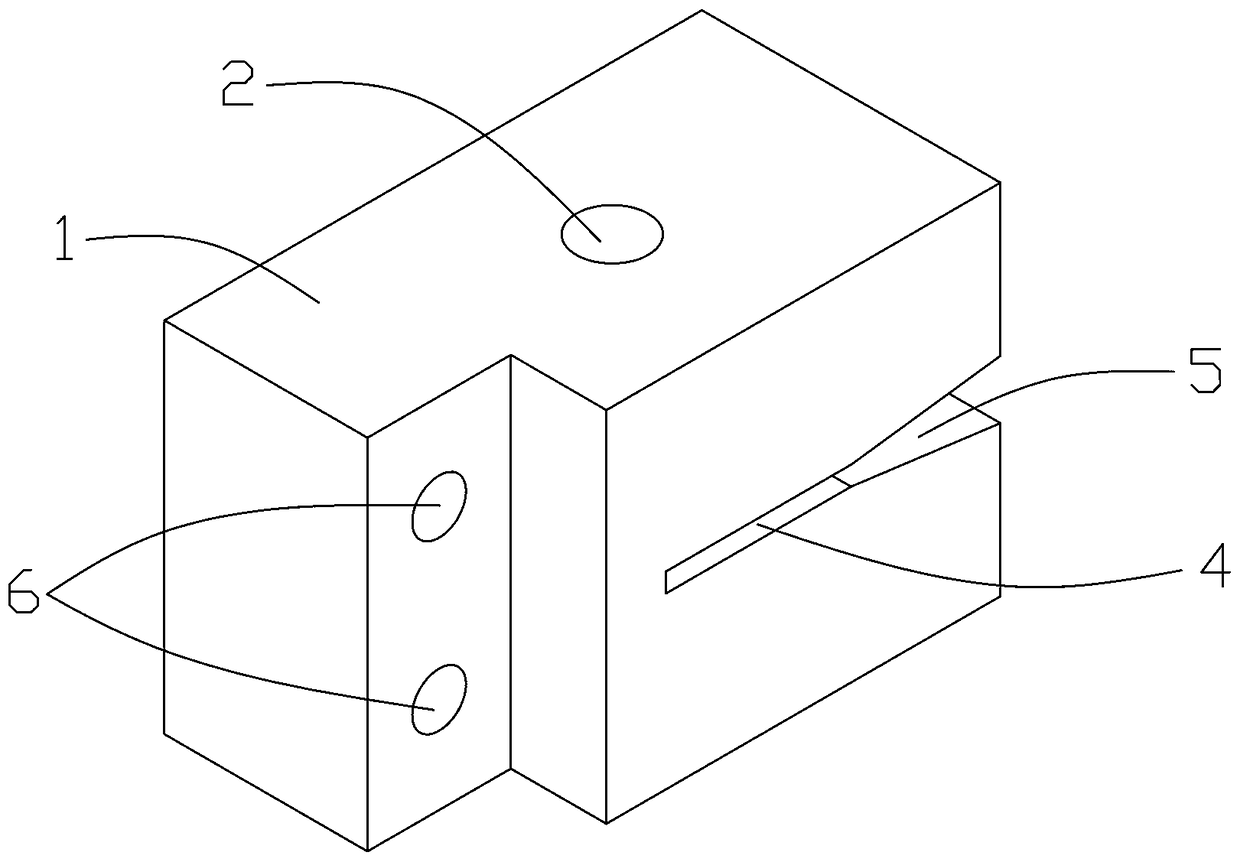
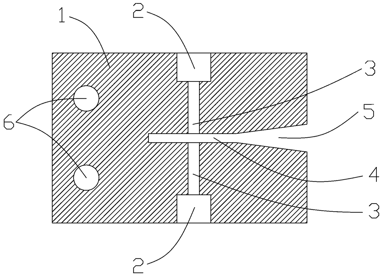
[0016] refer to figure 1 and figure 2 , a PCB board cursor printing device includes an exposure device for PCB board cursor printing, the cursor printing device also includes a base 1, the two opposite surfaces of the base 1 are respectively provided with an exposure device mounting groove 2, and the exposure device mounting groove An exposure device is respectively installed in 2, and the two exposure devices are arranged opposite to each other. The base 1 is also provided with an optical channel 3 connecting the mounting grooves of the two exposure devices, and a PCB board positioning slot 4 perpendicular to the optical channel. In this embodiment, the entrance of the PCB board positioning slot 4 is provided with a guiding slope 5 for guiding and positioning the PCB board. The guide slope 5 is convenient for the PCB board to be introduced into the...


PUM


Abstract

The invention relates to the field of optical equipment, in particular to a PCB cursor printing device and a printing method thereof, and the defect that the positioning cursors on the front side andthe back side of the same positions on a PCB in the prior art have displacement deviation is overcome. The device comprises exposure devices for printing PCB cursors, and the cursor printing device further comprises a base; exposure device mounting grooves are formed in the two opposite faces of the base respectively; one exposure device is arranged in the corresponding exposure device mounting groove, and the two exposure devices are oppositely arranged; and optical channels communicated with the two exposure device mounting grooves and PCB positioning grooves perpendicular to the optical channels are further arranged in the base. Two exposure devices are oppositely arranged on the PCB cursor printing device, and the optical channels of the two exposure devices coincide; and the two exposure devices carry out cursor printing on the upper surface and the lower surface of the same position of the PCB respectively, so that the positioning cursors on the front and back surfaces do not have displacement deviation.

Description

technical field [0001] The invention relates to the field of optical equipment, in particular to a PCB cursor printing device and a printing method thereof. Background technique [0002] In the PCB production process, before exposure, the inner layer of the multi-layer board cannot be positioned by mechanical drilling, but by optical marking. As the optical marking device has one upper and one lower, displacement deviation will occur during the movement process, which will directly affect the positioning accuracy. Contents of the invention [0003] The purpose of the present invention is to overcome the defect of displacement deviation of the positioning cursor on the front and back sides of the same position on the PCB in the prior art. [0004] The technical solution adopted for solving the technical problems proposed by the present invention is: the PCB board cursor printing device of the present invention includes an exposure device for PCB board cursor printing, and ...

Claims


Application Information

Patent Timeline
Patent Type & Authority Applications(China)
IPC IPC(8): G03F7/20H05K3/46
CPCH05K3/4638G03F7/20
Inventor 蔡志国余加辉钟惠良
Owner CAIZ OPTRONICS CORP
Learn More