Method and apparatus for line-of-sight antenna arrays

An antenna array and antenna sub-array technology, applied in diversity/multi-antenna systems, radio transmission systems, space transmit diversity, etc., can solve the problems that it is difficult to achieve the maximum or optimal channel capacity, and cannot be changed.

Active Publication Date: 2020-09-04
HUAWEI TECH CO LTD
View PDF3 Cites 0 Cited by
  • Summary
  • Abstract
  • Description
  • Claims
  • Application Information

AI Technical Summary

Problems solved by technology

[0007] The problem with using a ULA system is the antenna subarray configuration (i.e. the antenna subarray spacing D t and D r and the downward slope angle θ t and θ r ) is fixed during network operation and cannot be changed
Therefore, it is difficult to achieve maximum or optimal channel capacity under certain conditions

Method used


Image

  • Method and apparatus for line-of-sight antenna arrays
  • Method and apparatus for line-of-sight antenna arrays
  • Method and apparatus for line-of-sight antenna arrays

Examples


Embodiment Construction

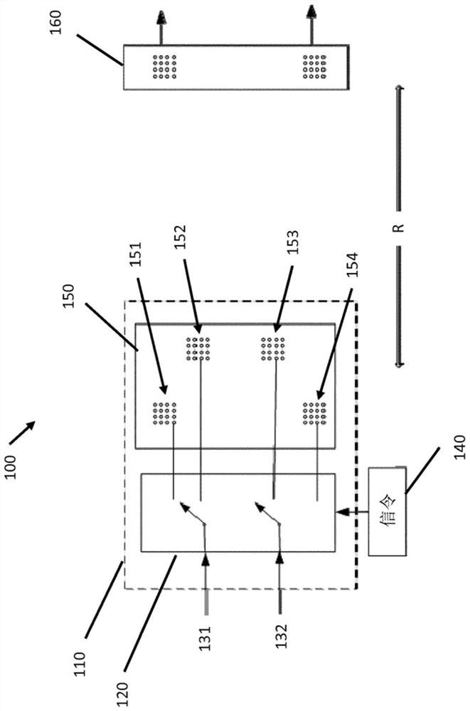
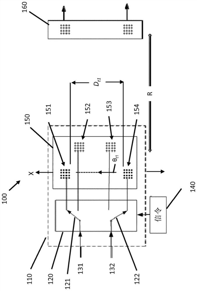
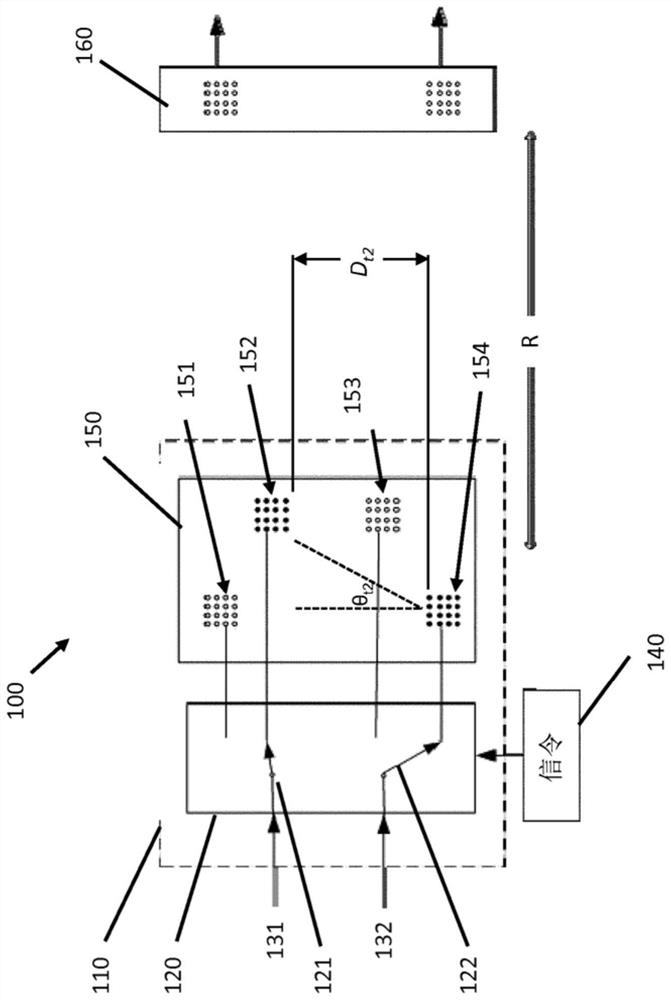
[0037] refer to figure 1 , aspects of the disclosed embodiments relate to dynamically configuring and / or reconfiguring one or more input signals to antenna subarrays of a network node or connections between different antenna subarrays of individual antenna elements or antenna elements. Rather than fixing the configuration of the antenna array, which typically includes the spacing between different antenna subarrays and the downtilt angle of the antenna array, aspects of the disclosed embodiments dynamically change the input signal to the antenna array to Connections between different antenna subarrays and / antenna elements of the antenna subarrays and / antenna elements. Configuration changes, also referred to herein as modes or configuration modes, are configured to achieve near-optimal channel capacity between transmitters and receivers in a Line-of-Sight (LOS) MIMO system. This dynamic change and reconfiguration can be controlled by signaling from network nodes.

[0038] fi...


PUM


Abstract

A network node includes an antenna array having a plurality of antenna sub-arrays. A switching device is coupled to the antenna array, the switching device being configured to connect at least two input signals to respective ones of the plurality of antenna sub-arrays. A processor is configured to determine a channel capacity, wherein based on the channel capacity, the processor is configured to control the switching device to switch a connection of the at least two input signals to different ones of the plurality of antenna sub-arrays to change one or more of an inter-distance between the respective ones of the plurality of antenna sub-arrays and a down-tilting angle of the antenna array.

Description

technical field [0001] Aspects of the present disclosure relate generally to wireless communication systems, and in particular, to dynamic switching of input signals to antenna subarrays. Background technique [0002] In the context of next-generation wireless networks, with around 2020 as the target commercialization time, mmWave radios are considered for building two types of backhaul nodes, aggregated and non-aggregated backhaul nodes. Millimeter waves are radio waves having wavelengths between about 1 mm and 10 mm corresponding to frequencies from about 30 GHz to 300 GHz. Due to the large available spectrum band, mmWave is preferred for carrying high bit rate data on the backhaul link. However, spectrum bands other than the band between 30GHz and 300GHz can also be used for the backhaul link. [0003] One way to increase the channel capacity of mmWave based backhaul links is to use Multiple-Input-Multiple-Output (MIMO) configurations, often using LoS MIMO, for backhaul...

Claims


Application Information

Patent Timeline
Patent Type & Authority Patents(China)
IPC IPC(8): H04B7/06H04B7/04H04B7/0413H04B7/0404
CPCH04B7/0413H04B7/0689H04B7/0691
Inventor 蔡涛马吉德·纳斯里·孔姆吉亨里克·伦奎思
Owner HUAWEI TECH CO LTD
Why Eureka
Try Eureka