Plate-beam-column shock (vibration) isolation connecting device

A connection device, beam-column technology, applied in the direction of earthquake resistance, floor slabs, building components, etc., can solve the problems of poor seismic performance of fully prefabricated floors, achieve the effects of seismic isolation, prevent stress concentration, and reduce earthquake force

Inactive Publication Date: 2018-11-27
四川建知科技有限公司
View PDF0 Cites 0 Cited by
  • Summary
  • Abstract
  • Description
  • Claims
  • Application Information

AI Technical Summary

Problems solved by technology

The current industry standard "Technical Regulations for Prefabricated Concrete Structures" (JGJ-2014) gives the design regulations for ordinary laminated floors. Due to the poor seismic performance of the current fully prefabricated floors, fully prefabricated floors are used for fully assembled buildings, that is, dry Buildings that are assembled by method can only be used in non-seismic or low-seismic fortification intensity projects

Method used


Image

  • Plate-beam-column shock (vibration) isolation connecting device
  • Plate-beam-column shock (vibration) isolation connecting device
  • Plate-beam-column shock (vibration) isolation connecting device

Examples


Embodiment Construction

[0019] Below in conjunction with accompanying drawing and specific embodiment the present invention will be described in further detail:

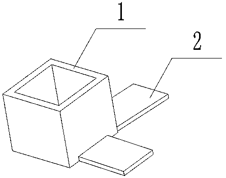
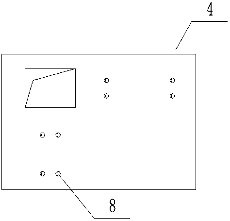
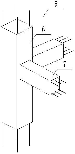
[0020] 1. A slab-beam-column isolation (vibration) connection device, including a slab-column isolation member 1, and a slab-beam cushion 2, the inner and outer sections of the slab-column isolation member 1 are square, and are arranged in different directions Two slab-beam cushions 2, the inner side of the slab-column isolation member 1 coincides with the section of the column unit 6, and the outer side coincides with the hole of the prefabricated floor unit 4, the slab-beam cushion 2 is on the slab-column isolation member 1 and the column unit 6 After the top is installed in place, it just contacts the top surface of the corresponding beam unit 7, and the width of the plate-beam cushion layer 2 is greater than the width of the top surface of the beam unit 7 (such as figure 1 , figure 2 , image 3 ). The plate-beam-column isolation (vi...


PUM


Abstract

The invention provides a plate-beam-column shock (vibration) isolation connecting device. The device comprises a plate-column isolation component and plate-beam under layers, wherein the inner side and outer side of the cross section of the plate-column isolation component both are squares, and the two plate-beam under layers are arranged in different directions; the inner side of the plate-columnisolation component is consistent with the cross section of a column unit, the outer side of the plate-column isolation component is consistent with a prefabricated floor unit hole, the plate-beam under layers are exactly in contact with the top faces of corresponding beam units after the plate-column isolation component is arranged in position on the column unit, and the width of the plate-beamunder layers is greater than that of the top faces of the beam units.

Description

technical field [0001] The invention designs an assembled building component, specifically a plate-beam-column isolation (vibration) connection device. Background technique [0002] With the rapid development of my country's economy and society, the acceleration of urbanization, the increasing pressure on environmental governance, and the emergence of labor shortages, the country has gradually put forward higher requirements for prefabricated buildings, requiring an increase in the proportion of prefabricated buildings in new buildings, and at the same time requiring an increase Prefabrication rate of prefabricated buildings. The current industry standard "Technical Regulations for Prefabricated Concrete Structures" (JGJ-2014) gives the design regulations for ordinary laminated floors. Due to the poor seismic performance of the current fully prefabricated floors, fully prefabricated floors are used for fully assembled buildings, that is, dry Buildings that cannot be assemble...

Claims


Application Information

Patent Timeline
Patent Type & Authority Applications(China)
IPC IPC(8): E04B5/04E04B1/98E04H9/02
CPCE04B5/04E04H9/021E04H9/022
Inventor 董智敏
Owner 四川建知科技有限公司
Why Eureka
Try Eureka