Eureka AIR delivers breakthrough ideas for toughest innovation challenges, trusted by R&D personnel around the world.

Machine part high-efficiency cleaning device

A technology for cleaning devices and mechanical parts, applied in the field of cleaning, can solve the problems of mechanical transmission influence, waste of time and manpower, inconvenient cleaning, etc., and achieve the effect of good cleaning effect and easy handling

Active Publication Date: 2018-11-30
HANGZHOU YONGDE ELECTRIC APPLIANCES
View PDF5 Cites 9 Cited by
  • Summary
  • Abstract
  • Description
  • Claims
  • Application Information

AI Technical Summary

Benefits of technology

This patented technology helps remove dirt from machinery's surfaces more effectively without damaging them or causing damage during maintenance work. It uses rotating tools with scraps on its surface to help it get ridged up easier while still being able to easily detach any remaining debris away after use.

Problems solved by technology

The technical problem addressed by this patented technology relates to improving the efficiency and automation of mechanisms used for removing dirt from surfaces during maintenance operations without causing excessive wear that could damage them overtime.

Method used


Image

  • Machine part high-efficiency cleaning device
  • Machine part high-efficiency cleaning device
  • Machine part high-efficiency cleaning device

Examples


Embodiment Construction

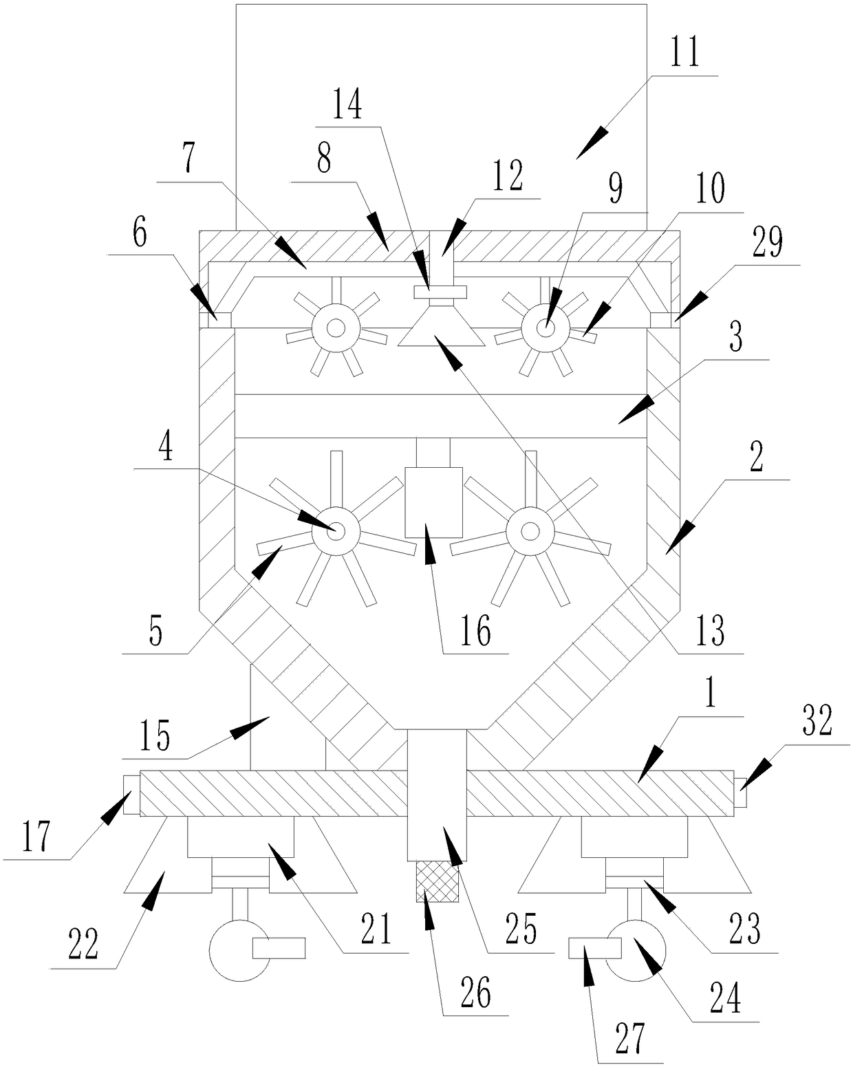
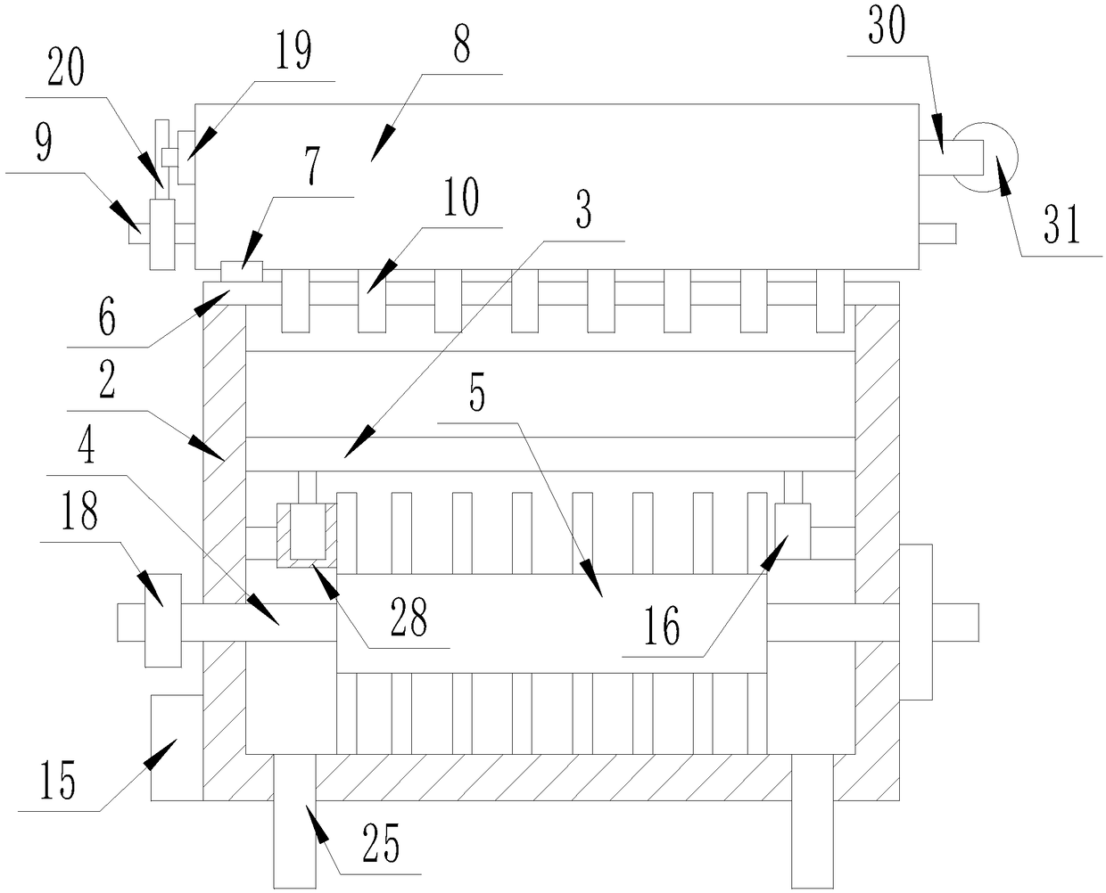
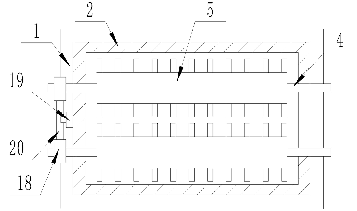
[0021] The present invention will be described in detail below with reference to the drawings, such as Figure 1-4 As shown, a high-efficiency cleaning device for mechanical parts includes a strip-shaped supporting base 1, a part cleaning mechanism is provided on the upper surface of the strip-shaped supporting base 1, and a moving mechanism is provided on the lower surface of the strip-shaped supporting base 1. The parts cleaning mechanism is mainly composed of a strip-shaped cleaning box body 2, a strip-shaped opening machined on the upper surface of the strip-shaped cleaning box body 2, and a strip-shaped opening provided in the strip-shaped cleaning box body 2. Tool carrier 3, a set of No. 1 horizontal round shafts 4 passing through the strip-shaped cleaning box 2 and below the tool carrier 3, nested on each No. 1 horizontal round shaft 4 and located in the strip-shaped cleaning box 2 No. 1 cleaning roller brush 5 inside, a set of horizontal slide rails 6 arranged on the up...


PUM


Abstract

The invention discloses a machine part high-efficiency cleaning device. The machine part high-efficiency cleaning device comprises a strip-type bearing base, wherein a part cleaning mechanism is arranged on the upper surface of the strip-type bearing base; and a moving mechanism is arranged on the lower surface of the strip-type bearing base. The machine part high-efficiency cleaning device has the beneficial effects that the machine part high-efficiency cleaning device clears stains on the surface of a tool are cleaned through rotation, scraping and vibration, has a good cleaning effect and is convenient to take and move, and the separation and collection of a cleaning solution are convenient.

Description


Claims


Application Information

Patent Timeline
Owner HANGZHOU YONGDE ELECTRIC APPLIANCES
Why Eureka
Eureka Blog
Learn More