Pneumatic cleaning die

A mold and pneumatic technology, applied in the field of pneumatic cleaning mold, can solve the problems of increasing cleaning cost, affecting work efficiency, complex structure, etc., and achieving the effect of solving secondary damage, improving ash removal efficiency, and increasing cleaning area

Inactive Publication Date: 2018-11-30
台聪
View PDF2 Cites 2 Cited by
  • Summary
  • Abstract
  • Description
  • Claims
  • Application Information

AI Technical Summary

Problems solved by technology

Traditional manual cleaning is easy to leave debris and water stains, which leads to mold corrosion and takes too long to clean, which seriously affects work efficiency. The existing cleaning machine is expensive, needs to disassemble the mold, complex structure, inconvenient operation, and greatly increased cleaning costs.

Method used


Image

  • Pneumatic cleaning die
  • Pneumatic cleaning die
  • Pneumatic cleaning die

Examples


Embodiment Construction

[0014] In order to enable those skilled in the art to better understand the technical solutions of the present invention, the present invention will be described more clearly and completely below in conjunction with the accompanying drawings in the embodiments. Of course, the described embodiments are only a part of the present invention. Not all, based on this embodiment, other embodiments obtained by those skilled in the art without creative efforts are all within the protection scope of the present invention.

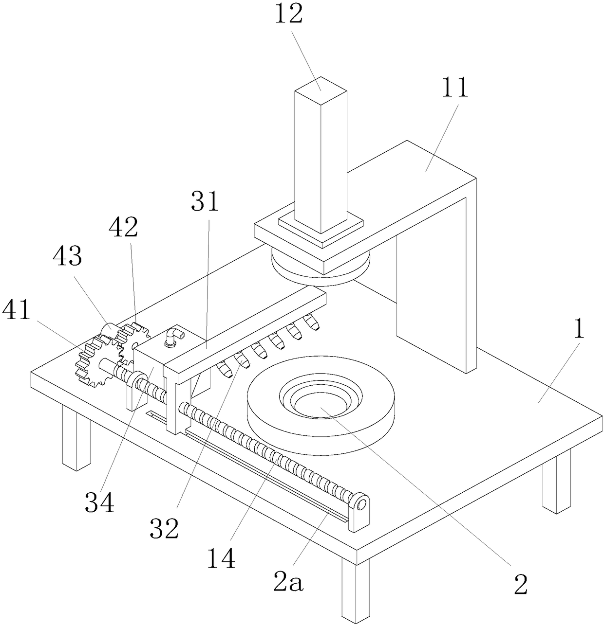
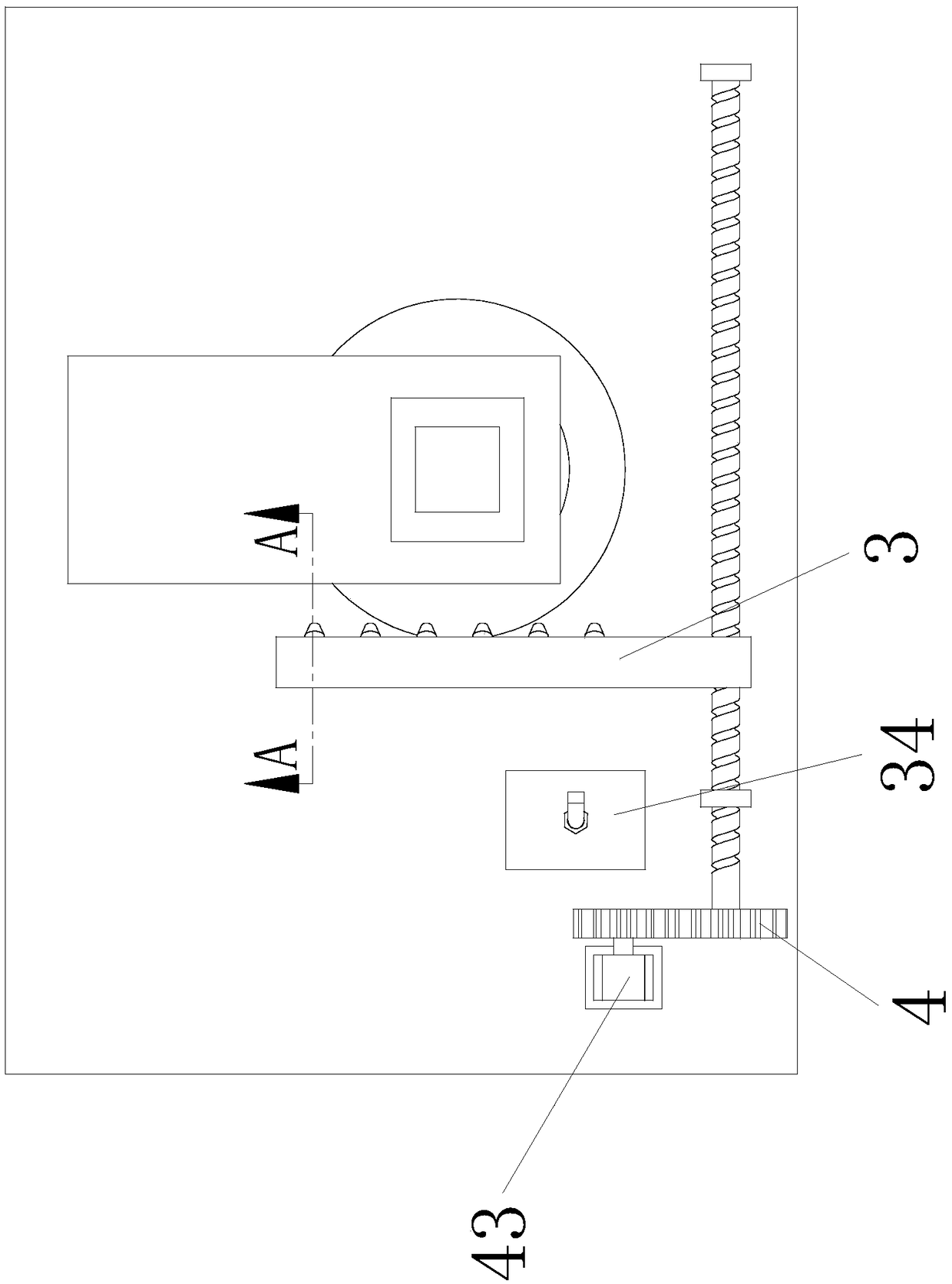
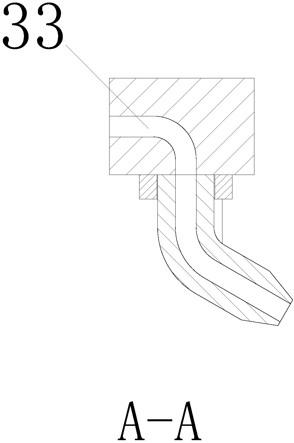
[0015] Such as Figure 1 to Figure 3 As shown, a pneumatic cleaning mould, comprising a workbench 1, a lower mold 2 positioned at the middle of the workbench 1, said workbench 1 is also equipped with a fixed frame 11, said fixed frame 11 is equipped with a hydraulic cylinder 12, and The hydraulic cylinder 12 is connected to the upper mold 13 that can cooperate with the lower mold 2, and is characterized in that it also includes a sliding air injection mechanism 3 alo...


PUM


Abstract

The invention relates to a pneumatic cleaning die. The die comprises a workbench and a lower die located in the middle of the workbench. The workbench is further provided with a fixing frame, and a hydraulic cylinder and an upper die connected with the hydraulic cylinder and matched with the lower die are installed on the fixing frame. The die further comprises a sliding water spraying mechanism in the length direction of the workbench and a lead screw which is matched with the water spraying mechanism and installed on the workbench. A power mechanism capable of making the lead screw rotate isfurther installed on the workbench. The die can be automatically cleaned, does not need to be disassembled and is simple in structure. An air jetting mechanism can completely cover the surface of thelower die, and the cleaning area is increased, so that the dust removal efficiency is improved, a cleaning fluid does not need to be used, the die is prevented from being corroded by surface residues, and secondary damage caused by residue cleaning to the die is effectively eliminated.

Description

technical field [0001] The invention relates to a stamping die cleaning technology, in particular to a pneumatic cleaning die. Background technique [0002] During the stamping process, the uneven surface of the lower die is prone to residues of debris and dust deposits, and the residue of debris on the upper die will automatically fall off to the lower die due to gravity, so the lower die needs to be cleaned regularly. Traditional manual cleaning is easy to leave debris and water stains, which leads to mold corrosion and takes too long to clean, which seriously affects work efficiency. The existing cleaning machine is expensive, needs to disassemble the mold, complex structure, inconvenient operation, and greatly increased cleaning costs. . Contents of the invention [0003] Now in order to solve the stamping die cleaning, the present invention proposes a pneumatic cleaning die. The technical problem to be solved by the present invention adopts the following technical s...

Claims


Application Information

Patent Timeline
Patent Type & Authority Applications(China)
IPC IPC(8): B08B5/02B08B13/00B30B15/00
CPCB08B5/02B08B13/00B30B15/0082
Inventor 台聪
Owner 台聪
Why Eureka
Try Eureka