
Low-cost washing machine power supply control system

A power control and washing machine technology, applied in the field of washing machines, can solve the problems of affecting the service life, easy to be contaminated with dust, difficult to adjust the length of the cable, etc., and achieve the effect of being easy to use when powered on

Inactive Publication Date: 2018-11-30
广州天亿科技有限公司
View PDF0 Cites 1 Cited by
  • Summary
  • Abstract
  • Description
  • Claims
  • Application Information

AI Technical Summary

Problems solved by technology

[0002] When the current washing machine is powered on, the plug needs to be plugged and installed on the power transmission base frame. The plug and the power transmission base frame are usually connected by friction fit. Unexpected power failure affects the use of the washing machine. Moreover, the length of the cable that is often connected to the washing machine is difficult to adjust, and it is often dragged on the ground, which is easy to be contaminated with dust and affects the service life.

Method used


Image

  • Low-cost washing machine power supply control system
  • Low-cost washing machine power supply control system
  • Low-cost washing machine power supply control system

Examples


Embodiment Construction

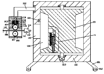
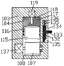
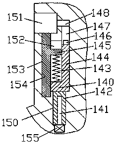
[0016] Combine below Figure 1-3 The present invention will be described in detail.

[0017] Reference Figure 1-3 According to an embodiment of the present invention, a low-cost washing machine power control system includes a base frame 100 and a connecting portion 114 used in conjunction with the base frame 100, and a slot is provided in the left end surface of the base frame 100 113. The right inner wall of the slot 113 is communicated with a steering cavity 122, a bogie 101 is rotatably installed in the steering cavity 122, a power transmission member 101 is arranged in the bogie 101, and the upper side of the slot 113 The left end surface of the base frame 100 is rotatably fitted with a link 102, the bottom end of the link 102 is fixedly provided with a fixing frame 103, and the front end surface of the fixing frame 103 is provided with a wire inlet groove 105 left and right. A first sliding cavity 136 extends up and down in the top wall of the wire inlet groove 105, a par...


PUM


Abstract

The invention discloses a low-cost washing machine power supply control system. The low-cost washing machine power supply control system comprises a base frame and a connection part cooperatively usedwith the base frame; a slot is formed in the end face of the left side of the base frame, a steering cavity is arranged on the inner wall of the right side of the slot in a communicated mode, a steering frame is rotatably and cooperatively installed in the steering cavity, and a power transmission component is arranged in the steering frame; a connection rod is rotatably and cooperatively installed on the portion, at the upper side of the slot, of the end face of the left side of the base frame, a fixing frame is fixedly arranged at the tail end of the bottom of the connection rod, a wire inlet slot is formed in the end face of the front side of the fixing frame in a left and right penetrating mode, a first sliding cavity is arranged in the top wall in the wire inlet slot in an up and down extending mode, a partition plate is installed in the first sliding cavity in a sliding fit mode, and a first elastic piece is installed between the top end of the partition plate and the top wall of the first sliding cavity in an ejection fit mode; and a second sliding cavity is arranged on the inner wall of the right side of the first sliding cavity in the mode of penetrating through the end face of the front side of the fixing frame, and a pushing handle fixedly connected with the partition plate is installed in the second sliding cavity in a sliding fit mode.

Description

Technical field [0001] The invention relates to the technical field of washing machines, in particular to a low-cost washing machine power control system. Background technique [0002] When the current washing machine is powered on, the plug needs to be inserted and installed on the power transmission base frame. The plug and the power transmission base frame are usually connected by friction fit. When the plug is accidentally touched, the plug is easy to fall off from the power transmission base frame. Unexpected power failure affects the use of the washing machine. Moreover, the length of the cable that is often connected to the washing machine is difficult to adjust, and it is often dragged on the ground, which is easy to contaminate dust and affect the service life. Summary of the invention [0003] The purpose of the present invention is to provide a low-cost washing machine power control system for overcoming the above-mentioned defects in the prior art. [0004] A low-cost w...

Claims


Application Information

Patent Timeline
Patent Type & Authority Applications(China)
IPC IPC(8): H01R13/60H01R13/633H01R13/639H01R13/72D06F39/00
CPCH01R13/639D06F39/00H01R13/60H01R13/633H01R13/72
Inventor 王国辉
Owner 广州天亿科技有限公司
Learn More