Wave beam forming method and terminal and base station

A beamforming method and beamforming technology, applied in diversity/multi-antenna systems, space transmit diversity, electrical components, etc., can solve the problem of limited beamforming gain, inability to jointly optimize physical antennas, and limited number of precoding matrices, etc. problem, to achieve the effect of large beamforming gain

Active Publication Date: 2018-12-04
SHANGHAI HUAWEI TECH CO LTD
View PDF1 Cites 4 Cited by
  • Summary
  • Abstract
  • Description
  • Claims
  • Application Information

AI Technical Summary

Problems solved by technology

[0004] In the prior art, the PMI information feedback method is used to calculate the beamforming weight value. Due to the limited size of the codebook indicated by the PMI, the number of precoding matrices that can be used for closed-loop spatial multiplexing is limited, and all available physical antennas cannot be combined. optimization, so the beamforming gain is also relatively limited, and a larger beamforming gain cannot be obtained

Method used


Image

  • Wave beam forming method and terminal and base station
  • Wave beam forming method and terminal and base station
  • Wave beam forming method and terminal and base station

Examples


Embodiment 1

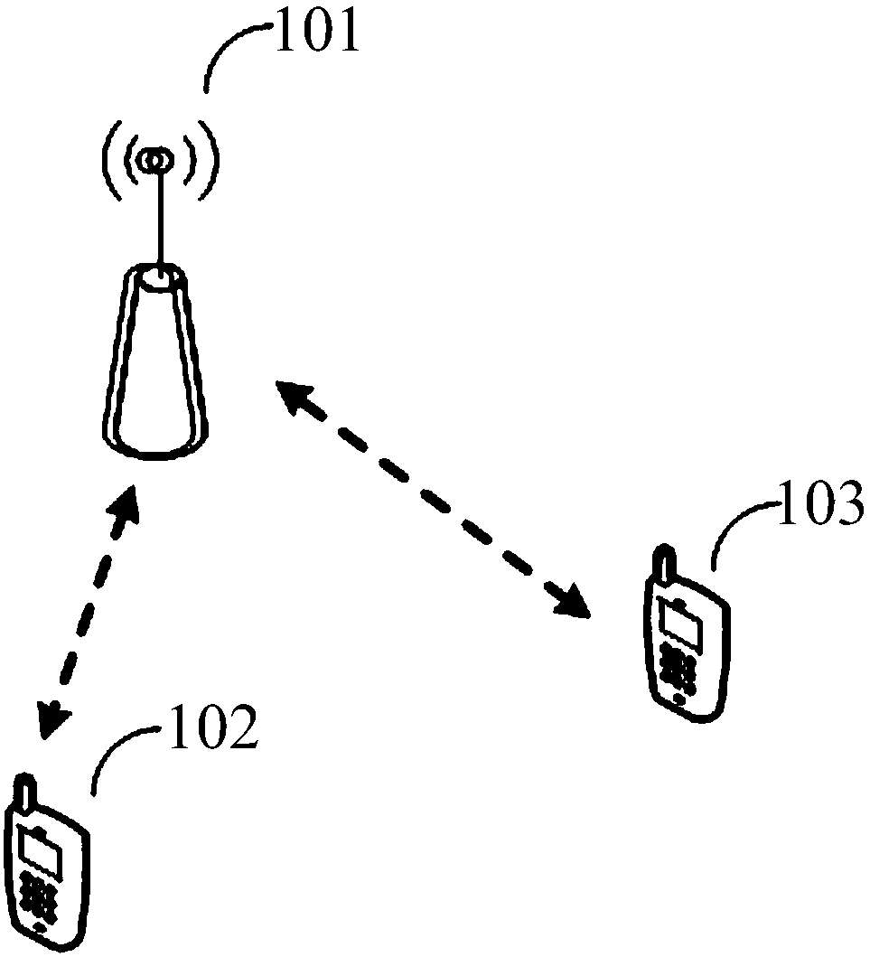
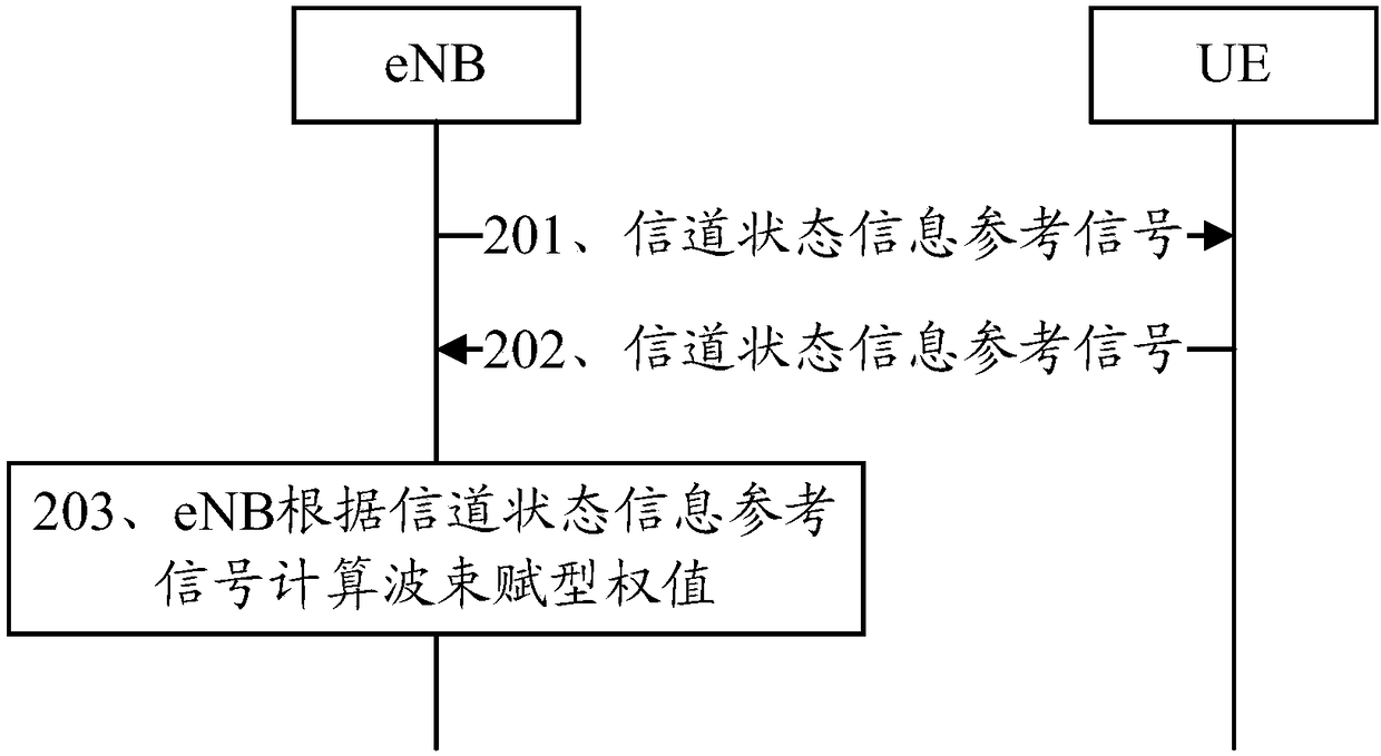
[0040] Embodiment one, such as figure 2 As shown, an embodiment of the beamforming method in the embodiment of the present application includes:

[0041] 201. The eNB sends a channel state information reference signal to the UE.

[0042] In this embodiment, in the FDD system, the eNB sends a channel state information reference signal to the UE. It should be noted that before sending the channel state information reference signal, the eNB needs a corresponding preparation stage for preparing the channel state information reference signal.

[0043] 202. The UE periodically sends the received channel state information reference signal to the eNB through the data channel according to the preset reporting period.

[0044] In this embodiment, after the UE receives the channel state information reference signal sent by the eNB, the UE directly sends the channel state information reference signal received by the UE itself to the eNB periodically through a data channel according to ...

Embodiment 2

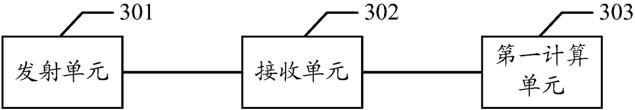
[0053] Embodiment 2, as shown in FIG. 3(a), an embodiment of the eNB in ​​the embodiment of the present application includes:

[0054] A transmitting unit 301, configured to send a channel state information reference signal to the UE;

[0055] The receiving unit 302 is configured to periodically receive the channel state information reference signal sent by the UE through a data channel;

[0056] The first calculating unit 303 is configured to calculate beamforming weights according to the channel state information reference signal.

[0057] Optionally, in a possible implementation manner, as shown in FIG. 3(b), the base station further includes: a second computing unit 307, wherein the second computing unit 307 is configured to perform Multi-user beamforming weight calculation, and multi-user beamforming weighting to obtain multi-user beamforming.

[0058] In addition, the transmitting unit 304, the receiving unit 305, and the first computing unit 306 are configured to perf...

Embodiment 3

[0060] Embodiment three, such as Figure 4 As shown, an embodiment of UE in the embodiment of this application includes:

[0061] The receiving unit 401 is configured to receive the channel state information reference signal sent by the eNB;

[0062] The sending unit 402 is configured to periodically send the channel state information reference signal to the eNB through a data channel according to a preset reporting period.

[0063] Optionally, in a possible implementation manner, the preset reporting period is associated with a configuration parameter, and the size of the preset reporting period can be dynamically adjusted according to the configuration parameter.

[0064] In this embodiment, it can be understood that the channel state information reference signal sent by the eNB to the UE is not exactly the same as the channel state information reference signal sent by the eNB to the UE. The former also includes channel state information such as downlink air interface loss ...


PUM


Abstract

An embodiment of the application discloses a wave beam forming method and terminal and base station that are used for obtaining great wave beam forming gain. The method disclosed in the embodiment ofthe application comprises the following steps: the base station is used for sending an information channel state information reference signal to the terminal, the base station is used for periodicallyreceiving the information channel state information reference signal sent via the terminal via a data information channel, and the base station is used for calculating wave beam forming weight according to the information channel state information reference signal.

Description

technical field [0001] The present application relates to the field of wireless communication systems, and in particular to a beamforming method, a terminal, and a base station. Background technique [0002] Beam forming (BF) is a signal preprocessing technology based on antenna array. Beam forming generates a directional beam by adjusting the weight coefficient of each array element in the antenna array, so as to obtain obvious array gain. . Therefore, beamforming technology has great advantages in expanding coverage, improving system capacity, and reducing interference. [0003] In a frequency division duplex (FDD) system, after the terminal receives the channel state information reference signal (CRS_RS) sent by the base station, the terminal can calculate the maximum Precoding matrix indicators (precoding matrix indicators, PMI) and rank indications (rank indication, RI) with the best performance. The terminal feeds back PMI and channel quality indication (CQI) inform...

Claims


Application Information

Patent Timeline
IPC IPC(8): H04B7/06
CPCH04B7/0452H04B7/0617H04B7/0626
Inventor 冯向兵宋毅
Owner SHANGHAI HUAWEI TECH CO LTD
Why Eureka
Try Eureka