Dimming control circuit under low brightness of LED lamp and control method thereof

A dimming control circuit and LED lamp technology, applied in the direction of light sources, electric light sources, electrical components, etc., can solve the problems of losing the dimming effect, failing to realize the dimming effect, and unable to realize the control of the output current, etc., to achieve the expansion of dimming Range, flexibility of use and convenience of effects

Active Publication Date: 2018-12-04
ZHEJIANG KAIYAO LIGHTING
View PDF8 Cites 0 Cited by
  • Summary
  • Abstract
  • Description
  • Claims
  • Application Information

AI Technical Summary

Problems solved by technology

However, there are many types of thyristor dimmers, and some thyristor dimmers will lose their dimming effect when the output current is adjusted below about 3%. The dimmer cannot control the output current, that is, the dimming effect cannot be achieved

Method used


Image

  • Dimming control circuit under low brightness of LED lamp and control method thereof

Examples


Embodiment

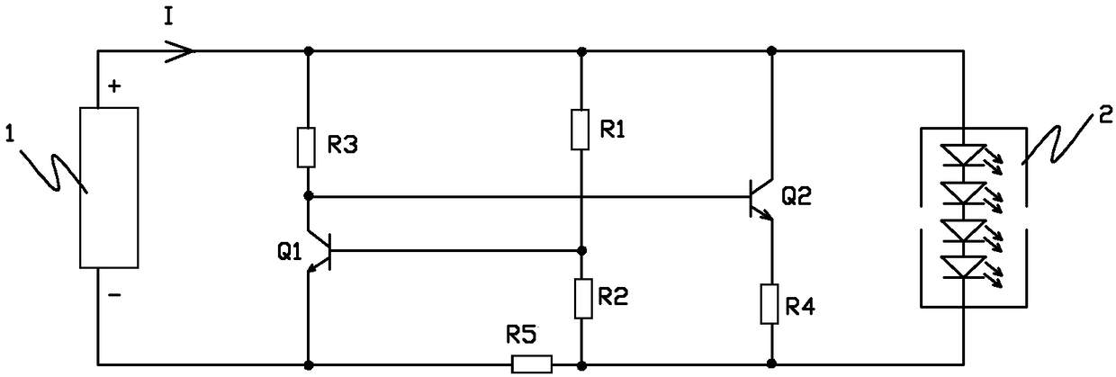
[0017] Embodiment: the dimming control circuit under the low brightness of the LED lamp of this embodiment, such as figure 1 As shown, including transistor Q1, transistor Q2 and dimming driver 1, the base of transistor Q1 is connected to the positive pole of the dimming driver through resistor R1, and the other is connected to one end of resistor R2, and the other end of resistor R2 is connected through resistor R5 It is connected to the emitter of the transistor Q1, the emitter of the transistor Q1 is connected to the negative pole of the dimming driver, the collector of the transistor Q1 is connected to the positive pole of the dimming driver through the resistor R3, and the collector of the transistor Q1 is connected to the base of the transistor Q2. The collector of the transistor Q2 is connected to the positive pole of the dimming driver and the positive pole of the LED lamp 2, the emitter of the transistor Q2 is connected to one end of the resistor R4, and the other end o...


PUM


Abstract

The invention relates to a dimming control circuit under low brightness of an LED lamp and a control method thereof. The dimming control circuit comprises a triode Q1, a triode Q2 and a dimming driver, wherein the base of the triode Q1 is connected with the positive electrode of the dimming driver through a resistor R1 and is also connected with the negative electrode of the dimming driver througha resistor R2; the collector and the emitter of the triode Q1 are connected with the positive electrode and the negative electrode of the dimming driver; the collector of the triode Q1 is connected with the base of the triode Q2; the collector and the emitter of the triode Q2 are connected with the positive electrode and the negative electrode of the dimming driver; and the collector and the emitter of the triode Q2 are connected with the positive electrode and the negative electrode of the LED lamp. When the output current I of the dimming driver is lower than a threshold current value I1 and higher than a threshold current value I2, both the triode Q1 and the triode Q2 are in a semi-conduction state, and along with changes of the output current I of the dimming driver, current flowing through the LED lamp presents curve changes, and the dimming effects of the LED lamp in a low current state are realized.

Description

technical field [0001] The invention relates to an LED lamp drive circuit, in particular to a dimming control circuit and a control method for the LED lamp at low brightness. Background technique [0002] The use of thyristor dimmers to adjust the brightness of lamps has been applied to the dimming circuits of incandescent lamps and energy-saving lamps earlier, and it is also a dimming method widely used in LED lamp dimming solutions. Its working principle is: use the thyristor dimmer to adjust the conduction angle of each half-wave of the AC to change the sinusoidal waveform, change the effective value of the AC input current, and at the same time drive the output current to change accordingly, so as to realize the LED lamp. Dimming effect. However, there are many types of thyristor dimmers, and some thyristor dimmers will lose their dimming effect when the output current is adjusted below about 3%. The dimmer cannot control the output current, that is, it cannot achieve ...

Claims


Application Information

Patent Timeline
Patent Type & Authority Applications(China)
IPC IPC(8): H05B33/08H05B44/00
CPCH05B45/10
Inventor 谭志鹏
Owner ZHEJIANG KAIYAO LIGHTING
Why Eureka
Try Eureka