PWM signal dimming circuit and method for three-phase AC power supply LED lamp

A PWM signal, LED lamp technology, applied in the use of semiconductor lamps, electrical components, etc., can solve the problems of no convenience, reduce costs, etc., and achieve the effect of convenient dimming, convenient use, and less peripheral circuits

Active Publication Date: 2022-04-15
HANGZHOU YIHUITONG TECH CO LTD
View PDF42 Cites 0 Cited by
  • Summary
  • Abstract
  • Description
  • Claims
  • Application Information

AI Technical Summary

Problems solved by technology

[0034] In view of the above situation, in order to overcome the above-mentioned defects of the prior art, especially the defect that the convenience of on-site construction and installation is not provided in the prior art, and at the same time the defects of positive and negative logic dimming are taken into account to reduce the cost, the present invention provides three The PWM signal dimming circuit and method of phase-to-AC power supply LED lamps effectively solve the above-mentioned problems

Method used


Image

  • PWM signal dimming circuit and method for three-phase AC power supply LED lamp
  • PWM signal dimming circuit and method for three-phase AC power supply LED lamp

Examples


Embodiment 1

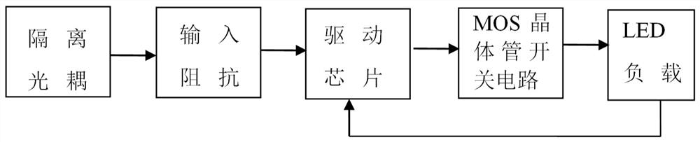
[0054] Such as figure 1 As shown, the basic way to realize the dimming function in this embodiment is: after the external PWM signal is input through the isolated optocoupler circuit, after passing through the input impedance matching circuit, a dimming signal voltage is generated and provided to the driver chip circuit, and the driver chip circuit The output of the MOS transistor switch circuit is controlled according to the change of the dimming signal voltage and the change of the current signal collected by the LED load circuit, and the MOS transistor switch circuit controls the power change of the LED load circuit. Specifically: when the duty cycle of the PWM signal of the external dimming controller becomes larger, the voltage of the dimming signal collected by the dimming control pin Is of the driver chip U2 becomes larger after the isolation optocoupler circuit and the input impedance matching circuit , the output voltage of the output power control pin OUT of the driv...

Embodiment 2

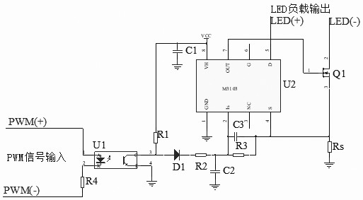
[0056] Such as figure 2 As shown, in this embodiment, the pins of the driver chip U2 are defined as follows: pin 1 is the negative terminal of the power supply, grounded, pin 2 is the dimming control pin, connected with resistors and capacitors, and pin 3 is suspended, which is an empty tube Pin 4 is the current sampling pin, which is connected to the current sampling resistor and controlled by pin 2. The pin 5 of the driver chip U2 is the load output pin, and the pin 6 of the driver chip U2 is suspended, which is an empty pin. Pin 7 of U2 is the output control pin, and pin 8 of the driver chip U2 is the positive terminal of the power supply, which is connected to VCC.

[0057] The model of isolated optocoupler U1 is PC817, the driver chip U2 is M3103 of Hefei Yunshan Photoelectric Technology Co., Ltd., the model of diode D1 is 1N4001, the model of MOS transistor Q1 is 1N80, the resistance of resistor R1 is 1K ohms, the resistance of R2 is 100 ohms, and the resistance of The...

Embodiment 3

[0059]Similar to the above two embodiments, in this embodiment, a PWM signal dimming method and circuit for a three-phase 380V tunnel LED lamp driver chip interface, including an isolated optocoupler U1, a driver chip U2, a diode D1, a MOS Transistor Q1, resistor R1, resistor R2, resistor R3, resistor R4, resistor Rs, capacitor C1, capacitor C2, capacitor C3, etc. The pin 1 of the isolated optocoupler U1 is connected to the positive phase of the external PWM signal input PWM, the pin 2 of the isolated optocoupler U1 is connected to one end of the resistor R4, and the other end of the resistor R4 is connected to the negative phase of the external PWM signal input PWM , pin 3 of the isolated optocoupler U1 is connected to pin 8 of the driver chip U2 through a resistor R1, and is connected to the positive end of the diode D1 at the same time, and pin 4 of the isolated optocoupler U1 is connected to the power ground. The negative end of the diode D1 is connected to pin 2 of the dr...


PUM


Abstract

The invention discloses a PWM (Pulse Width Modulation) signal dimming circuit and method for a three-phase AC (Alternating Current) power supply LED (Light Emitting Diode) lamp, in particular to a PWM signal dimming method and circuit for a three-phase 380V tunnel LED lamp driving chip, comprising a dimming input signal processing circuit, an isolation optocoupler circuit, a driving chip output control circuit and the like, the circuit is simple in structure, good in dimming linearity, convenient to use, high in reliability and compatible with mainstream dimming input signals in the market, the simple impedance matching circuit is matched with a dimming interface of a driving chip special for a three-phase 380V tunnel LED lamp, a positive and negative logic dimming method is compatible, digital intelligent dimming application is achieved, and the circuit has the advantages of being reliable in use, low in cost and the like. Dimming is convenient, the number of peripheral circuits is small, and cost is low.

Description

technical field [0001] The present invention belongs to the electronic field of tunnel lighting, and specifically relates to a PWM signal dimming circuit and method for three-phase AC power supply LED lamps, and more specifically, to a PWM signal dimming method and method for driving chips of three-phase 380V tunnel LED lamps. circuit. Background technique [0002] As a new generation of green and efficient lighting source, LED is more and more widely used. LED lighting technology has the characteristics of high light efficiency, good color rendering, long life, energy saving and environmental protection. It is constantly replacing traditional lighting technology. In order to create a more comfortable lighting atmosphere and To save energy, LED tunnel lighting modules using three-phase 380V have begun to be applied. Among them, the research on LED lighting dimming technology is extremely important. The existing three-phase 380V LED tunnel lighting usually uses 0-10V analog v...

Claims


Application Information

Patent Timeline
Patent Type & Authority Applications(China)
IPC IPC(8): H05B45/325H05B45/40
CPCH05B45/325H05B45/40Y02B20/30
Inventor 徐超董强薛浩魏正毅屠中烈鲁华
Owner HANGZHOU YIHUITONG TECH CO LTD
Why Eureka
Try Eureka