
Pedal-type toilet

A foot-operated toilet technology, which is applied in home appliances, sanitary equipment, applications, etc., can solve the problem that the toilet is not well solved, achieve good anti-slip effect, improve comfort, and reduce inertial impact

Inactive Publication Date: 2018-12-07
ANHUI POLYTECHNIC UNIV MECHANICAL & ELECTRICAL COLLEGE
View PDF12 Cites 1 Cited by
  • Summary
  • Abstract
  • Description
  • Claims
  • Application Information

AI Technical Summary

Problems solved by technology

[0005] The toilet involved in the above-mentioned comparative document does not well solve the problems raised by the present application, therefore, the structure of the toilet needs to be re-designed more reasonably

Method used


Image

  • Pedal-type toilet
  • Pedal-type toilet
  • Pedal-type toilet

Examples


Embodiment 1

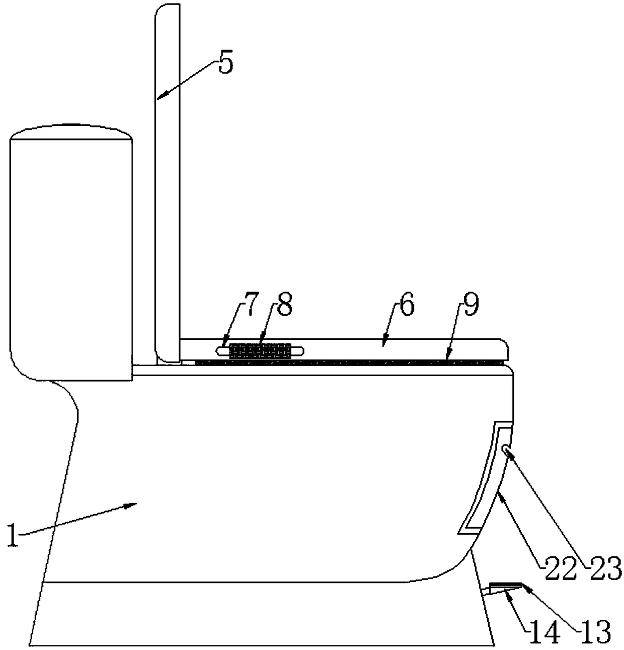
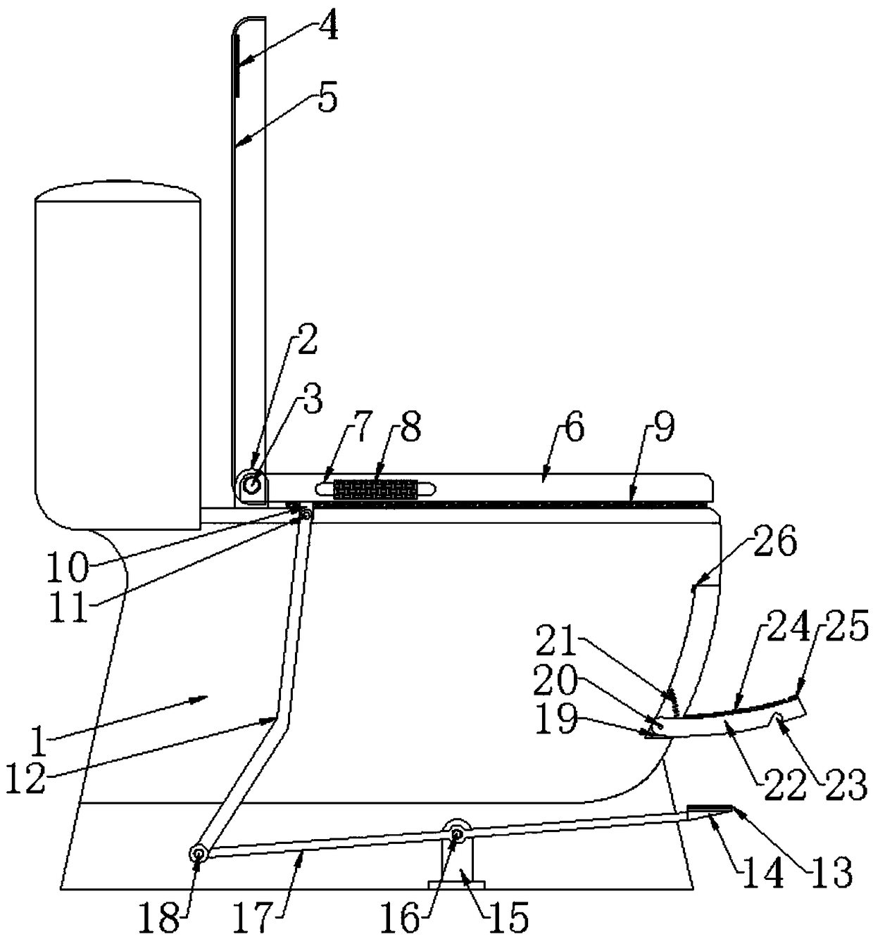
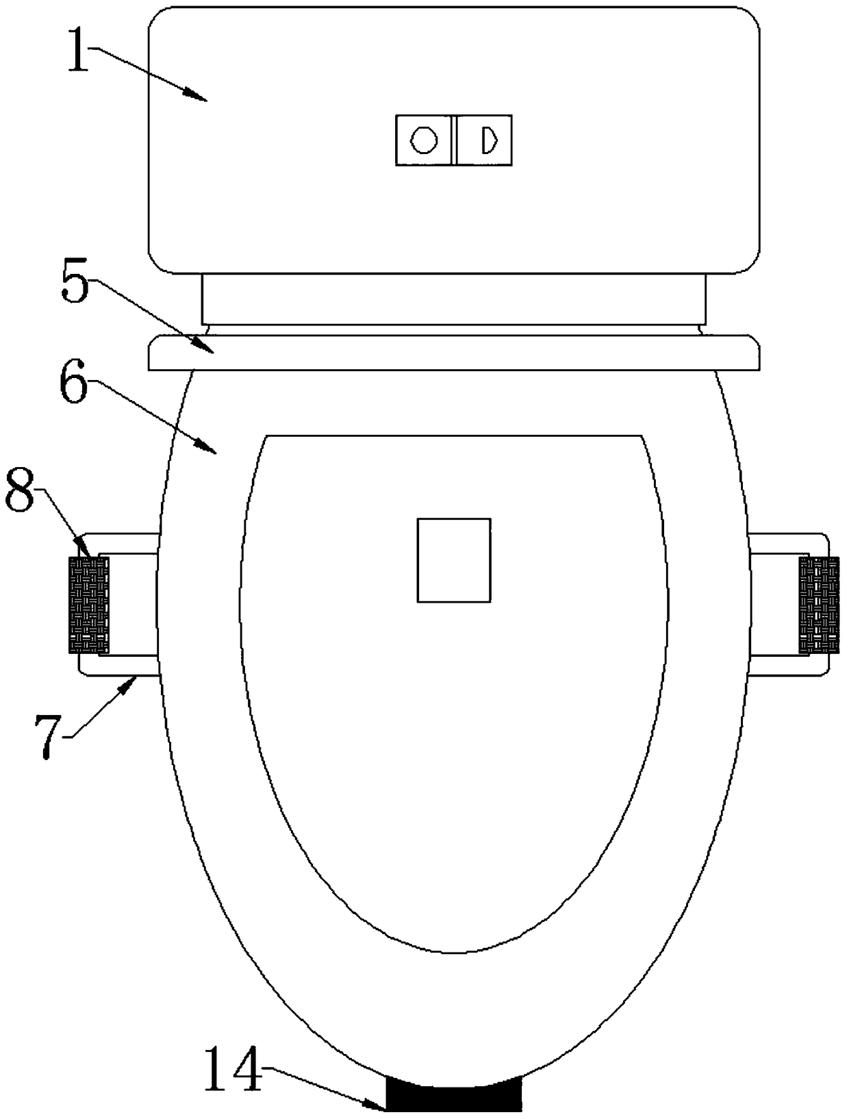
[0021] Such as Figure 1 to Figure 3 As shown, a foot-operated toilet includes a toilet body 1, a toilet cover 5 and a toilet seat 6, the toilet seat 6 is located inside the toilet seat 5, and the upper part of the toilet body 1 is provided with a hinge support 2 And rotate and install with toilet cover 5 and toilet pad 6 respectively by rotating shaft one 3, the bottom of described toilet pad 6 is provided with hinge support two 10, and the front side lower end of described toilet body 1 is provided with pedal 14, and described Lever 17 is welded on pedal 14, and the middle part of described lever 17 is provided with hinge support three 15, and described lever 17 is installed by rotating shaft three 16 and hinge support three 15, and the other end of described lever 17 passes through rotating shaft Five 18 is rotatably equipped with curved rod 12, and described curved rod 12 runs through the upper end surface of toilet body 1 and is rotatably connected with hinge support two ...

Embodiment 2

[0025] Such as Figure 1 to Figure 3 As shown, a foot-operated toilet includes a toilet body 1, a toilet cover 5 and a toilet seat 6, the toilet seat 6 is located inside the toilet seat 5, and the upper part of the toilet body 1 is provided with a hinge support 2 And rotate and install with toilet cover 5 and toilet pad 6 respectively by rotating shaft one 3, the bottom of described toilet pad 6 is provided with hinge support two 10, and the front side lower end of described toilet body 1 is provided with pedal 14, and described Lever 17 is welded on pedal 14, and the middle part of described lever 17 is provided with hinge support three 15, and described lever 17 is installed by rotating shaft three 16 and hinge support three 15, and the other end of described lever 17 passes through rotating shaft Five 18 is rotatably equipped with curved rod 12, and described curved rod 12 runs through the upper end surface of toilet body 1 and is rotatably connected with hinge support two ...


PUM


Abstract

The invention discloses a pedal-type toilet, and relates to the technical field of bathroom equipment. The toilet comprises a toilet body, a toilet cover and a toilet seat; the toilet seat is arrangedin the toilet cover, the upper portion of the toilet body is provided with a first hinge support base and rotatably installed with the toilet cover and the toilet seat through a first rotating shaftseparately, and the bottom of the toilet seat is provided with a second hinge support base; the lower end of the front side of the toilet body is provided with a pedal, a lever is welded to the pedal,a third hinge support base is arranged in the middle of the lever, the lever is rotatably installed with the third hinge support base through a third rotating shaft, and a cranked rod is rotatably installed at the other end of the lever through a fifth rotating shaft, penetrates through the upper end face of the toilet body and is rotatably connected with the second hinge support base through a second rotating shaft; a foot pad plate is rotatably installed at the front side of the toilet body through a fourth hinge support base and a fourth rotating shaft, a support soft pad is arranged at the lower side of the toilet seat, and armrests are arranged at the two sides of the toilet seat. When the toilet is in use, a user can lift the toilet seat simply by slightly stepping on the pedal, andthe situation that the toilet seat is lifted with hands is avoided.

Description

technical field [0001] The invention relates to the technical field of bathroom equipment, in particular to a pedal toilet. Background technique [0002] In daily life, the toilet is an indispensable daily necessities. However, when using the toilet at ordinary times, people need to decide whether to lift the toilet seat and use it again according to the situation of urination or defecation, which is not only unhygienic, but also breeds direct contact between bacteria and hands. [0003] Chinese patent application number 201610605945.5 discloses a toilet, including a top cover, a seat ring, a toilet body and a connecting shaft. The toilet body is provided with two first hinge supports with first hinge holes, and the two ends of the seat ring have The second hinge hole, the two ends of the upper cover are provided with the third hinge hole close to the second hinge hole, one end of the connecting shaft is provided with a handle, and the other end passes through the hinge hol...

Claims


Application Information

Patent Timeline
Patent Type & Authority Applications(China)
IPC IPC(8): A47K13/10A47K13/24A47K17/02
CPCA47K13/10A47K13/24A47K17/028
Inventor 金燕红李奇辰刘刚何东华徐健吴豫超
Owner ANHUI POLYTECHNIC UNIV MECHANICAL & ELECTRICAL COLLEGE
Learn More