Supercharge Your Innovation With Domain-Expert AI Agents!

High-light chamfer machining method

A technology of high-gloss chamfering and processing method, which is applied in metal processing, metal processing equipment, metal processing machinery parts, etc., and can solve problems such as low work efficiency

Active Publication Date: 2018-12-07
GUANGDONG EVERWIN PRECISION TECH
View PDF5 Cites 1 Cited by
  • Summary
  • Abstract
  • Description
  • Claims
  • Application Information

AI Technical Summary

Problems solved by technology

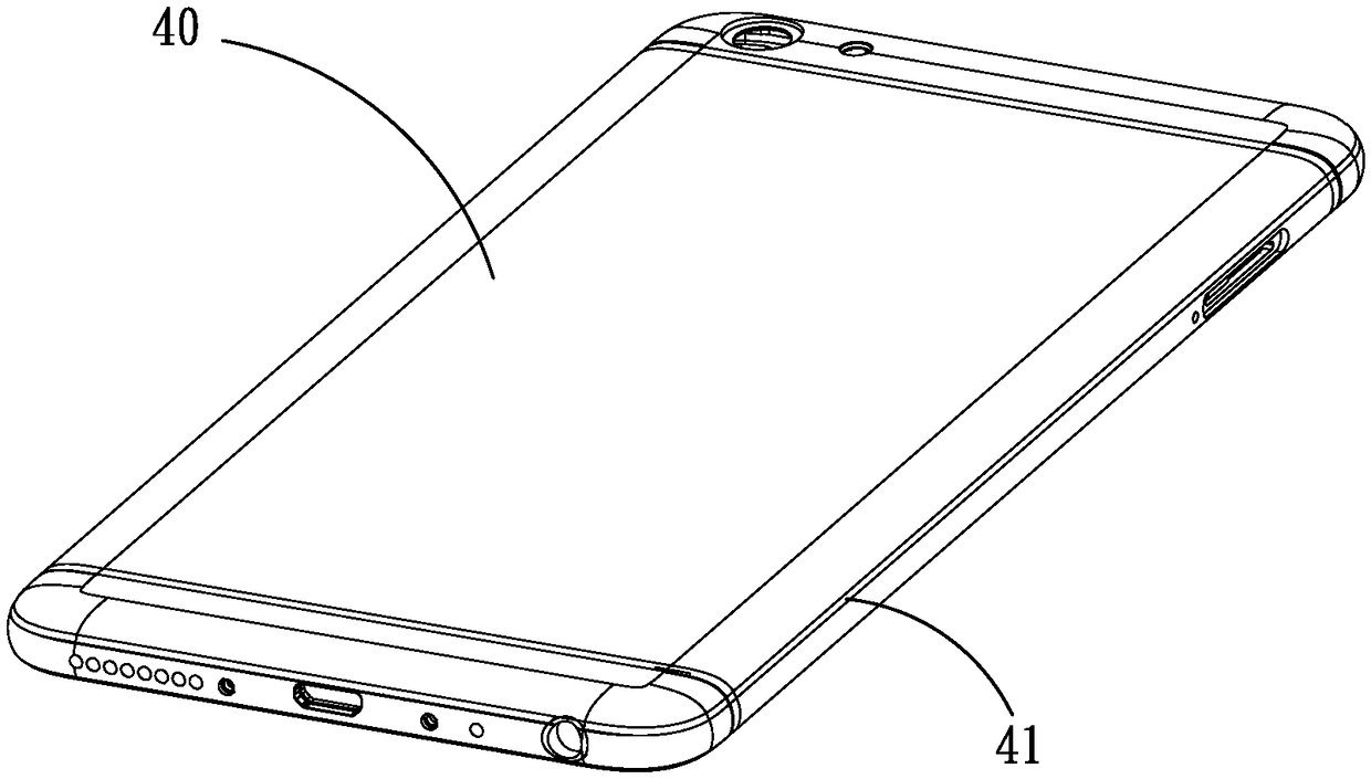
[0003] For example, if figure 1 and figure 2 As shown, the outer surface of the electronic product appearance part 40 is provided with a concave highlight chamfer 41, for equal radius of curvature (the radius of curvature of each place of the highlight chamfer is R) and equal width (the upper end line of each place of the highlight chamfer The distance between the lower end line and the highlight chamfer is D), if the path of the highlight chamfer 41 of the target is irregular (that is, the highlight chamfer is not on the same plane as a whole, for example figure 2 As shown, the paths of the high-gloss chamfers at the two ends of the electronic product appearance part 40 are upturned h) compared to the path of the middle section. 3D modeling of the parts to obtain the finished product model with high-gloss chamfering, and then use the 3D surface profiling method to let the tool follow the surface contour of the 3D model to carry out the entity of the appearance part 40 of the electronic product without high-gloss chamfering. Cutting to get the target highlight chamfer 41, its work is very inefficient

Method used


Image

  • High-light chamfer machining method
  • High-light chamfer machining method
  • High-light chamfer machining method

Examples


Embodiment Construction

[0035] In order to facilitate the understanding of the present invention, the present invention will be described more fully below with reference to the associated drawings. Preferred embodiments of the invention are shown in the accompanying drawings. However, the present invention can be embodied in many different forms and is not limited to the embodiments described herein. On the contrary, these embodiments are provided to make the understanding of the disclosure of the present invention more thorough and comprehensive.

[0036] It should be noted that when an element is referred to as being “fixed” to another element, it can be directly on the other element or there can also be an intervening element. When an element is referred to as being "connected to" another element, it can be directly connected to the other element or intervening elements may also be present.

[0037] Unless otherwise defined, all technical and scientific terms used herein have the same meaning as...


PUM


Abstract

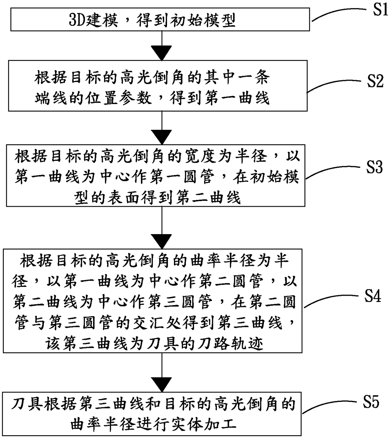
The invention relates to a high-light chamfer machining method. The method comprises the following steps that 3D modeling is carried out to obtain an initial model; a first curve is obtained, a firstround tube is made by using the first curve, the radius R1 of the first round tube is equal to the width D of the high-light chamfer of the target, and a second curve is obtained; a second round tubeis made according to the first curve, a third round tube is made according to the second curve, the radius R2 of the second round tube and the radius R3 of the third round tube are both equal to the curvature radius R of the high-light chamfer of the target, and the second round tube and the third round tube are intersected at the outside of the initial model to form a third curve; and a tool is used for performing surface cutting machining on a solid of an electronic product appearance piece without the high-light chamfer according to the third curve and the curvature radius R of the high-light chamfer of the target. According to the high-light chamfer machining method, the tool is used for performing one-time machining and forming of the high-light chamfer of the solid of a product according to the third curve and the curvature radius of the high-light chamfer of the target, so that the working efficiency is improved.

Description

technical field [0001] The invention relates to the technical field of processing electronic product appearance parts, in particular to a processing method for high-gloss chamfering. Background technique [0002] As the public becomes more interested in the appearance, texture, appearance and performance of 3C electronic products (3C electronic products usually refer to computers, tablet computers, mobile phones, digital cameras, walkmans, electronic dictionaries, audio-visual players, or digital audio players, etc.), In recent years, all walks of life are striving to pursue and design the novelty and innovation of product appearance to attract consumers' attention. At present, the high-gloss chamfer design of product appearance has always been favored by consumers, but for manufacturing companies, how to make high-gloss chamfers exquisite and improve the yield and efficiency of chamfer processing has become a major problem for enterprises. [0003] For example, if figure ...

Claims


Application Information

Patent Timeline
Patent Type & Authority Applications(China)
IPC IPC(8): B23Q15/007G06F17/50
CPCB23Q15/007G06F30/17
Inventor 林海桂黄浩蔡杰成陈高洪彭加国罗卫强陈义
Owner GUANGDONG EVERWIN PRECISION TECH
Features
  • R&D
  • Intellectual Property
  • Life Sciences
  • Materials
  • Tech Scout
  • Unparalleled Data Quality
  • Higher Quality Content
  • 60% Fewer Hallucinations
Learn More