
Automotive windshield rain protection system

A windshield and front windshield technology, applied in vehicle maintenance, vehicle parts, vehicle cleaning, etc., can solve the problems of unclear vision, impact of vision, and inability to touch the windshield, so as to achieve clear vision and solve problems. The effect of blurred vision and accelerated air flow

Inactive Publication Date: 2018-12-11
ALLPOWER DISPLAY CO LTD
View PDF9 Cites 3 Cited by
  • Summary
  • Abstract
  • Description
  • Claims
  • Application Information

AI Technical Summary

Problems solved by technology

[0005] Aiming at the defects in the prior art, the present invention provides an automobile windshield rainproof system to solve the problem of unclear vision caused by rainwater pouring on the automobile windshield
[0007] The existing windshield rainproof systems are all "governance" methods to solve the problem of windshield rainwater, that is: after the rainwater hits the windshield, the rainwater on the surface of the windshield is cleaned, and the rainwater drenched on the windshield On the glass, even if it is cleaned in time, it will have a certain impact on the vision, and this application adopts a "preventive" method to solve the problem of rain on the windshield, that is, a high-pressure fan is used to form a strong windshield in front of the car's front windshield. Wind wall, when the rain is close to the strong wind wall, it will be blown up by the strong wind wall and blown away along the wind direction, so that the rain cannot touch the windshield, ensuring a clear view, and completely solving the problem of rainwater falling on the windshield of the car The problem of unclear vision caused by the glass; and, when the fan is working, it can speed up the air flow in the front of the car, taking into account the heat dissipation function of the car engine and water tank

Method used


Image

  • Automotive windshield rain protection system
  • Automotive windshield rain protection system
  • Automotive windshield rain protection system

Examples


Embodiment Construction

[0022] Embodiments of the technical solutions of the present invention will be described in detail below in conjunction with the accompanying drawings. The following examples are only used to illustrate the technical solution of the present invention more clearly, and therefore are only examples, and should not be used to limit the scope of protection of this patent.

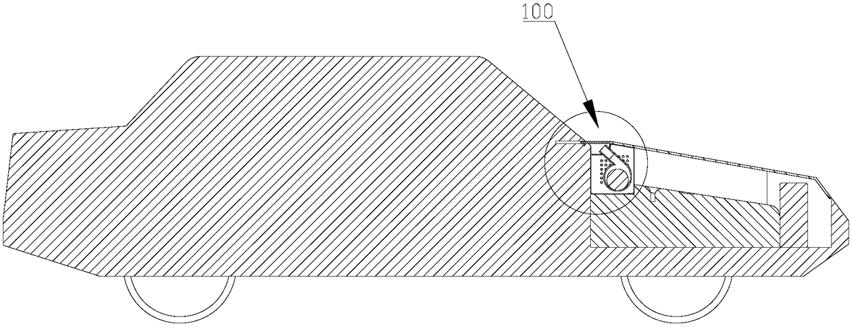
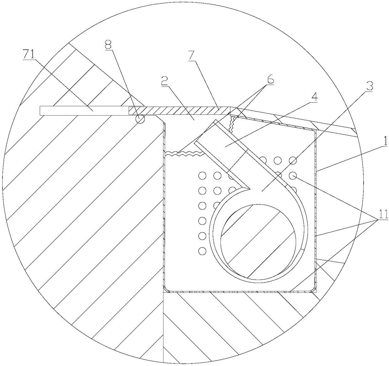
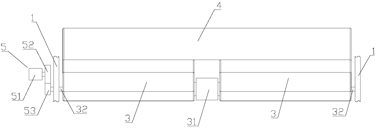
[0023] Such as Figure 1-Figure 4 As shown, the embodiment of the present invention provides an automobile windshield rainproof system, which includes a fan assembly 100 , and the fan assembly 100 includes a fan housing 1 , several high-pressure fans 3 and air guide slots 4 .

[0024] refer to figure 1 and figure 2 , the fan housing 1 is installed in the front of the front windshield of the automobile, the rear part of the front cover of the automobile and the rear part of the upper side housing of the fan housing 1 are all provided with an air outlet 2 along the horizontal direction, and the front of the aut...


PUM


Abstract

An automotive windshield rain protection system includes a fan assembly; The fan assembly comprises a fan housing and a plurality of high-pressure fans, wherein the fan housing is installed in a vehicle head in front of a front windshield of an automobile; an air outlet is transversely arranged at a rear part of a front cover of the automobile and a rear part of an upper side housing of the fan housing; the air outlet on the front cover of the automobile is coincident with the air outlet on the upper side housing of the fan housing; The high-pressure fans are arranged side by side in the fan housing, the air outlets of the high-pressure fans face the air outlets, and the wind blown out by the high-pressure fans forms a strong wind wall in front of the front windshield of the automobile. When the rainwater approaches the strong wind wall, the rainwater will be blown up by the strong wind wall and blown away along the wind direction, so that the rainwater can not touch the windshield, the vision is clear, and the problem that the vision is not clear caused by the rainwater spraying on the windshield of a car is completely solved.

Description

technical field [0001] The invention relates to the technical field of automobiles, in particular to an automobile windshield rainproof system. Background technique [0002] The traditional car wiper includes a wiper arm and a wiper blade installed on the wiper arm. The wiper blade is attached to the windshield of the car, and the wiper arm drives the wiper blade to swing to remove rain, snow and dirt on the windshield. . The main disadvantages of the traditional wiper are as follows: (1) the swing will affect the driver's line of sight, and there are potential safety hazards; Sand and gravel may scratch the windshield. [0003] In order to solve the above problems, the Chinese utility model patent CN2186686 specification discloses a jet wiper on the windshield window directly in front of the cab of a motor vehicle. The pipeline connected with the compressed air source is formed, so that the pressure air flow is continuously rushed out from the air nozzle of the air spray...

Claims


Application Information

Patent Timeline
Patent Type & Authority Applications(China)
IPC IPC(8): B60S1/54B60K11/06
CPCB60K11/06B60S1/54
Inventor 李星光谢光勤
Owner ALLPOWER DISPLAY CO LTD
Learn More