
Calibration plate detection method

A detection method and a technology for calibrating plates, which are applied in image analysis, instruments, graphics and image conversion, etc., can solve problems such as the need to improve the detection method of calibration plates, and achieve the effect of saving calibration time, improving calibration accuracy and improving calibration efficiency.

Active Publication Date: 2021-07-16
IAUTO (SHANGHAI) CO LTD
View PDF5 Cites 0 Cited by
  • Summary
  • Abstract
  • Description
  • Claims
  • Application Information

AI Technical Summary

Problems solved by technology

[0006] However, the calibration plate detection method in the prior art still needs to be improved

Method used


Image

  • Calibration plate detection method
  • Calibration plate detection method
  • Calibration plate detection method

Examples


Embodiment Construction

[0035] It can be seen from the background technology that the existing calibration plate detection method still needs to be improved.

[0036] Now analyze in conjunction with a calibration plate detection method, the calibration plate detection method includes: obtaining the first type of calibration plate image captured by the corresponding vehicle-mounted panoramic camera; identifying the preset first type of calibration plate image from the corresponding first type of calibration plate image The position coordinates of the number of sign dots in the image coordinate system of the corresponding vehicle-mounted panoramic camera; determine the initial external parameters of the corresponding vehicle-mounted panoramic camera.

[0037] The accuracy of the initial external parameters obtained by the above-mentioned calibration board detection method is low, which leads to poor mosaic effect of the surrounding images of the vehicle. The reasons for the analysis are as follows:

[...


PUM


Abstract

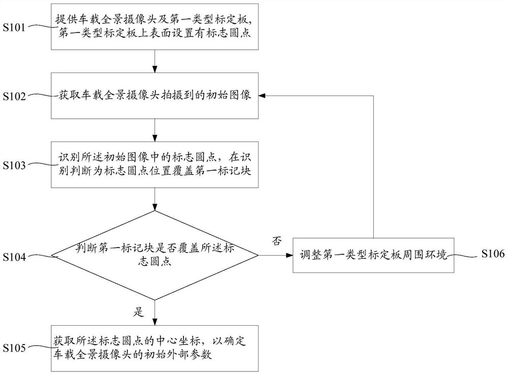
A method for detecting a calibration board, comprising: providing a vehicle-mounted panoramic camera and a first type of calibration board, the first type of calibration board is provided with mark dots on the upper surface; obtaining an initial image captured by the vehicle-mounted panoramic camera; identifying the mark circle in the initial image Points, cover the first mark block at the position of the mark dot identified and judged; judge whether the first mark block covers the mark dot, if the first mark block covers the mark dot, then obtain the center coordinates of the mark dot to determine The initial external parameters of the vehicle-mounted panoramic camera. If the first mark block does not cover the mark dot, adjust the surrounding environment of the first type of calibration board, and obtain the image captured by the vehicle-mounted panoramic camera again, and enter the next cycle until the first mark Block cover sign dots. The invention is convenient for the operator to judge whether the position recognition of the mark dot is accurate, conveniently finds the interfering objects in the environment that cause misidentification, helps to improve the calibration efficiency, saves the calibration time, and improves the calibration accuracy.

Description

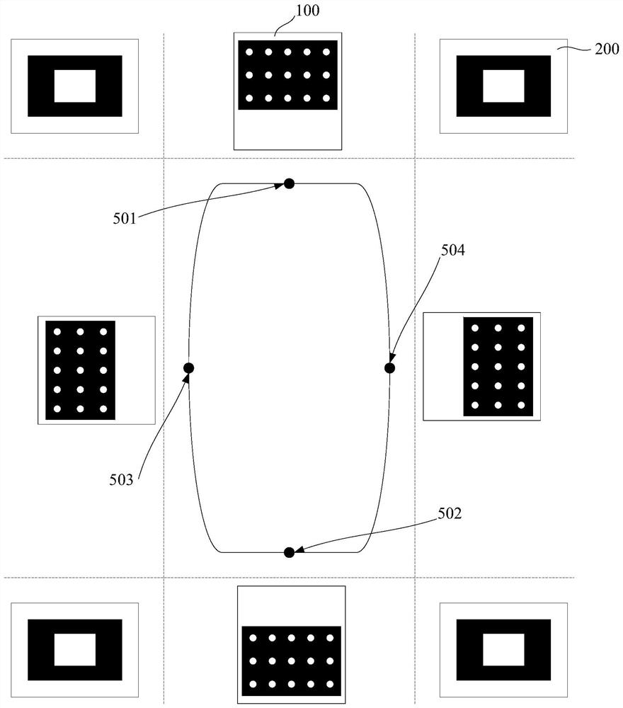
technical field [0001] The invention relates to the technical field of automotive electronics, in particular to a calibration board detection method. Background technique [0002] Calibration Target can be used to correct lens distortion in applications such as machine vision, image measurement, photogrammetry, and 3D reconstruction. [0003] The geometric model of the camera can be obtained through the calculation of the camera with a fixed-pitch pattern array plate and the calculation of the calibration algorithm, so as to obtain high-precision measurement and reconstruction results. [0004] The vehicle-mounted panoramic camera is used to collect images around the vehicle. The vehicle-mounted panoramic camera includes a front camera on the front side of the vehicle, a rear camera on the rear side of the vehicle, a left camera on the left side of the vehicle, and a right camera on the right side of the vehicle. After obtaining the images around the vehicle, the image stit...

Claims


Application Information

Patent Timeline
Patent Type & Authority Patents(China)
IPC IPC(8): G06T7/136G06T7/187G06T7/80G06T3/40
CPCG06T3/4038G06T7/136G06T7/187G06T7/80
Inventor 余旭根孙亚锋葛金炬谈旭峰
Owner IAUTO (SHANGHAI) CO LTD
Learn More