A self-locking orthodontic bracket
An orthodontic bracket and self-locking technology, applied in the direction of brackets, etc., can solve the problems of difficult installation and easy loss of cover body, and achieve the effect of good opening and closing, and firm structure
- Summary
- Abstract
- Description
- Claims
- Application Information
AI Technical Summary
Problems solved by technology
Method used
Image

Examples
specific Embodiment 1
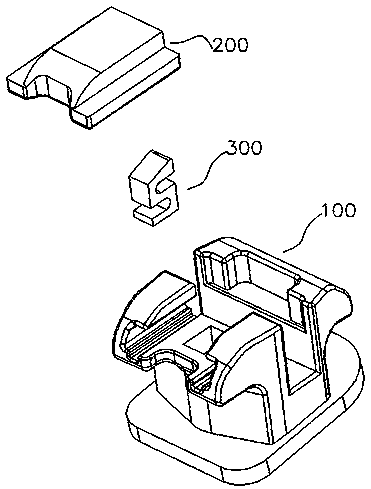
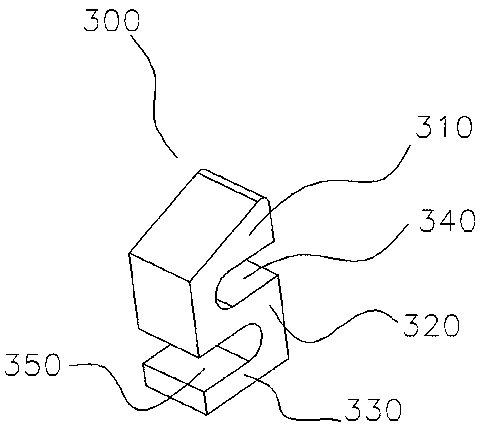
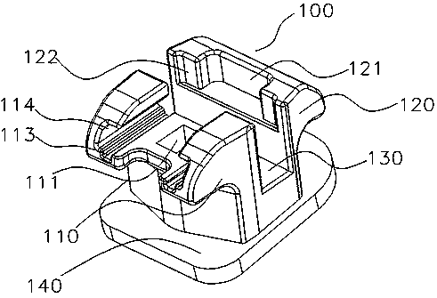
[0050] Such as Figure 1-6 As shown, the elastic member 300 is in an "S" shape, and the locking protrusion 310 at the locking end is a smooth protrusion. At the bottom of 300, the locking protrusion 310 is tilted up relative to the positioning end 330, and the two neutral positions of the transition part 320 of the "S"-shaped elastic member 300 are the first avoidance position 340 and the second avoidance position 350 from top to bottom. The elastic member 300 is installed in the avoidance cavity 111 of the main body 100, so that the positioning end 330 is in contact with the bottom of the avoidance cavity 111, and the locking protrusion 310 protrudes from the avoidance cavity.
[0051] After the elastic member 300 is installed in the avoidance cavity 111 of the main body 100, the cover body 200 is installed again. The slide rail and the guide rail of the cover body 200 respectively slide and push the cover body 200 along the chute 114 and the guide groove 113 of the main body...
specific Embodiment 2
[0057] Such as Figure 7-8 As shown, the positioning end 330 of the elastic member 300 is a flat plate, and the locking end is a tilt at one end of the positioning end. 180°, wherein the most preferred range is 30°-60°. The elastic member 300 is in a “T” shape, and the locking end of the elastic member 300 can be pressed to move the locking end downward.
[0058] It should be noted that the range of angles mentioned here is only used to describe the magnitude of the warp, without any specific limitation.
[0059] The principle of this embodiment is the same as that of the first embodiment, and will not be repeated here.
specific Embodiment 3
[0061] Such as Figure 9-10 As shown, the elastic member 300 is in the shape of a question mark as a whole, and the locking end is approximately in the shape of a "U" or "V". connected so that the elastic member 300 is in the shape of a "question mark". The escape cavity 111 of the main body 100 matched with the elastic member 300 is an inverted "h"-shaped cavity. When the locking end is squeezed, the locking protrusion 310 bends toward the groove bottom of the avoiding cavity 111, and the first avoiding position The 340 position is narrowed. The elastic member 300 is matched with the avoidance cavity 111 on the main body 100 , and there is a groove under the avoidance cavity 111 matching the positioning end 330 of the elastic member 300 for assembling the positioning end 330 .
[0062] The principle of this embodiment is the same as that of the first embodiment, and will not be repeated here.
PUM
 Abstract
Description
Claims
Application Information
 - R&D
- Intellectual Property
- Life Sciences
- Materials
- Tech Scout
- Unparalleled Data Quality
- Higher Quality Content
- 60% Fewer Hallucinations
Browse by: Latest US Patents, China's latest patents, Technical Efficacy Thesaurus, Application Domain, Technology Topic, Popular Technical Reports.
© 2025 PatSnap. All rights reserved.Legal|Privacy policy|Modern Slavery Act Transparency Statement|Sitemap|About US| Contact US: help@patsnap.com