Hollow blade

A hollow vane, vane technology, applied in the components of pumping devices for elastic fluids, non-variable displacement pumps, machines/engines, etc., can solve the wake loss, impair the aerodynamic and acoustic performance of the vane, intensify the airflow Boundary layer separation and other issues to achieve the effect of reducing wake loss

Active Publication Date: 2018-12-18
FANS TECH ELECTRIC CO LTD
View PDF8 Cites 4 Cited by
  • Summary
  • Abstract
  • Description
  • Claims
  • Application Information

AI Technical Summary

Problems solved by technology

However, the blades in the prior art are usually made by bending one plate, and the two ends of the plate are welded to each other, which will damage the aerodynamic performance and acoustic performance of the blade, aggravate the separation of the boundary layer of the airflow, and cause excessive wake loss

Method used


Image

  • Hollow blade
  • Hollow blade
  • Hollow blade

Examples


Embodiment Construction

[0018] The following will clearly and completely describe the technical solutions in the embodiments of the present invention with reference to the accompanying drawings in the embodiments of the present invention. Obviously, the described embodiments are only some, not all, embodiments of the present invention. Based on the embodiments of the present invention, all other embodiments obtained by persons of ordinary skill in the art without making creative efforts belong to the protection scope of the present invention.

[0019] In order to enable those skilled in the art to better understand the solution of the present invention, the present invention will be further described in detail below in conjunction with the accompanying drawings and specific embodiments.

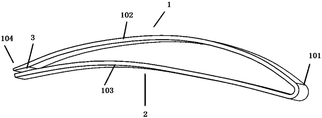
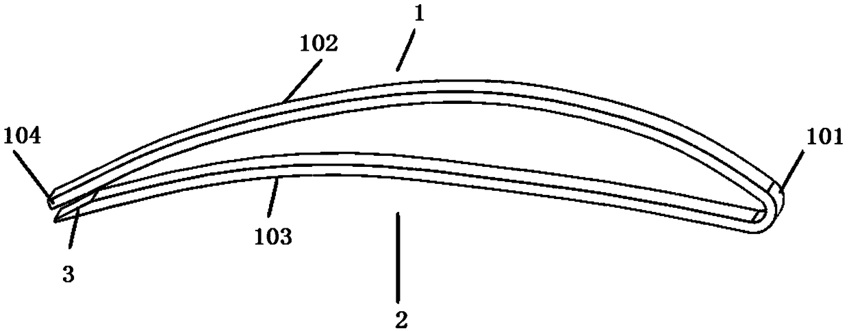
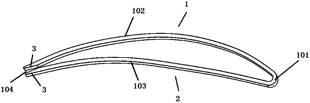
[0020] Please refer to Figure 1 to Figure 4 , figure 1 It is a structural schematic diagram of the first specific embodiment of the hollow blade provided by the present invention; figure 2 It is a schematic stru...


PUM


Abstract

The invention discloses a hollow blade used for a centrifugal fan impeller. The hollow blade comprises a first vane plate forming a pressure surface and a second vane plate forming a suction surface,the rear ends/rear end of the first vane plate and/or the second vane plate are/is provided with connecting portions/a connecting portion for mutual connection, and the thicknesses of each connectingportion are gradually reduced from front to back. The rear end of at least one of the first vane plate and the second vane plate of the hollow blade is provided with the connecting portion, the thickness of the rear end of each connecting portion is thin, the thickness of the back edge of the hollow blade is smaller after the first vane plate is connected with the second vane plate, and the trailing edge loss of the hollow blade is further reduced.

Description

technical field [0001] The invention relates to the technical field of fluid machinery, in particular to a hollow blade. Background technique [0002] The blades of the hollow structure have the advantages of light weight and high strength, which can reduce the weight of the fan and reduce the energy consumption of the fan. However, the blades in the prior art are usually made by bending a plate, and the two ends of the plate are welded to each other, which will damage the aerodynamic performance and acoustic performance of the blade, aggravate the separation of the boundary layer of the airflow, and cause excessive wake loss. [0003] Therefore, how to reduce the wake loss of the hollow blade is a technical problem to be solved by those skilled in the art. Contents of the invention [0004] It is an object of the present invention to provide a hollow blade with a thinner trailing edge and less wake loss. [0005] To achieve the above object, the present invention provid...

Claims


Application Information

Patent Timeline
Patent Type & Authority Applications(China)
IPC IPC(8): F04D29/30F04D29/28F04D29/66
CPCF04D29/281F04D29/30F04D29/666
Inventor 陈宗华袁小永
Owner FANS TECH ELECTRIC CO LTD
Why Eureka
Try Eureka