a centrifugal impeller

A technology of centrifugal impeller and centrifugal fan, applied in non-variable-capacity pumps, pump elements, components of pumping devices for elastic fluids, etc., can solve the problems of reduced impeller efficiency, reduced impeller efficiency, separation loss, etc. The effect of reducing secondary flow loss and eddy current loss, reducing impeller noise and improving efficiency

Active Publication Date: 2021-02-12
FANS TECH ELECTRIC CO LTD
View PDF9 Cites 0 Cited by
  • Summary
  • Abstract
  • Description
  • Claims
  • Application Information

AI Technical Summary

Problems solved by technology

During the rotation of the impeller, the width of the airflow channel gradually increases, and the airflow will thicken the boundary layer due to the decrease in flow velocity and increase in pressure, and separation will occur at the rear of the boundary layer, forming a separated vortex area, resulting in separation loss, resulting in Reduced impeller efficiency
In addition, the pressure of the airflow on the suction surface of the blade is low, and the pressure of the airflow on the pressure surface is high. The airflow between two adjacent blades will be shifted from the pressure surface to the suction surface, forming a secondary flow, and then generating vortices in the blade channel. Affect the efficiency of the centrifugal fan and increase the noise of the centrifugal fan
Although setting short impellers between long blades can reduce the boundary layer separation and secondary flow above the suction surface of long blades, boundary layer separation and secondary flow will still occur above the suction surface of short blades, reducing the efficiency of the impeller. This makes it impossible to completely change the uneven distribution of the flow field in the prior art

Method used


Image

  • a centrifugal impeller
  • a centrifugal impeller
  • a centrifugal impeller

Examples


Embodiment Construction

[0024] The following will clearly and completely describe the technical solutions in the embodiments of the present invention with reference to the accompanying drawings in the embodiments of the present invention. Obviously, the described embodiments are only some, not all, embodiments of the present invention. Based on the embodiments of the present invention, all other embodiments obtained by persons of ordinary skill in the art without making creative efforts belong to the protection scope of the present invention.

[0025] In order to enable those skilled in the art to better understand the solution of the present invention, the present invention will be further described in detail below in conjunction with the accompanying drawings and specific embodiments.

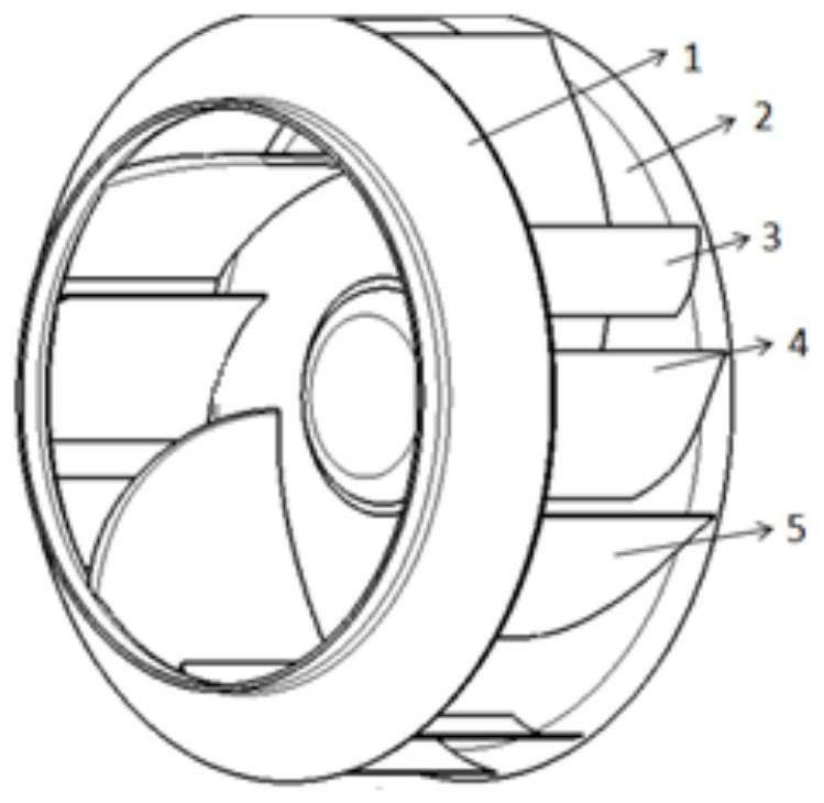
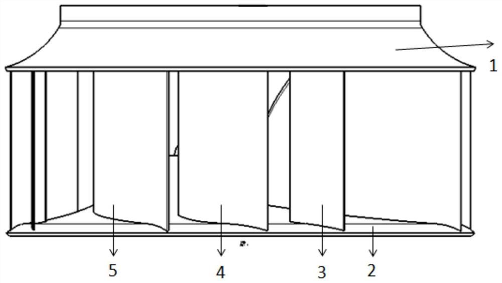
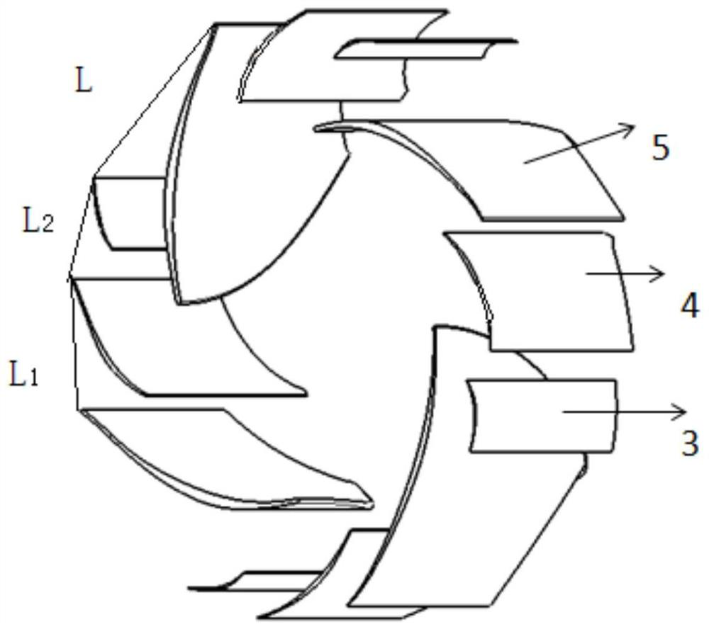
[0026] Please refer to Figure 1 to Figure 4 , figure 1 Schematic diagram of the structure of the centrifugal impeller provided by the present invention; figure 2 is the side view of the centrifugal impeller; i...


PUM


Abstract

The invention discloses a centrifugal impeller, which is used for a centrifugal fan without a volute. It includes a wheel cover and a wheel disc. There are multiple blade groups arranged between the wheel cover and the wheel disc. The blades and two or more short blades, all the short blades in the blade group are located on one side of the long blade suction surface, and the long blades and all the short blades have an airfoil profile. There are two or more short blades in one blade group, and the airflow between the long blades is restricted by multiple short blades. Each short blade can avoid secondary flow and suction on the suction surface of the previous blade. The eddy current near the surface greatly reduces the secondary flow and eddy current loss in the centrifugal impeller, so as to improve the efficiency of the centrifugal impeller and reduce the noise of the impeller.

Description

technical field [0001] The invention relates to the technical field of fluid machinery, in particular to a centrifugal impeller. Background technique [0002] The volute-less fan has the advantages of large air volume and simple structure, and is widely used in air coolers, exhaust fans, air conditioners and other equipment. The volute-less fan has low efficiency during the rotation of the impeller due to the lack of a volute outside the impeller. The power loss in the fan mainly comes from separation loss, impact loss, secondary flow loss and wake loss. [0003] In the prior art, a short blade is arranged between two long blades to reduce separation loss and secondary flow loss. During the rotation of the impeller, the width of the airflow channel gradually increases, and the airflow will thicken the boundary layer due to the decrease in flow velocity and increase in pressure, and separation will occur at the rear of the boundary layer, forming a separated vortex area, re...

Claims


Application Information

Patent Timeline
Patent Type & Authority Patents(China)
IPC IPC(8): F04D29/28F04D29/30F04D29/66
CPCF04D29/282F04D29/30F04D29/666F04D29/667
Inventor 李帅领
Owner FANS TECH ELECTRIC CO LTD
Why Eureka
Try Eureka