
a centrifugal impeller

A technology of centrifugal impeller and wheel cover, applied in the direction of non-variable pumps, pump elements, components of pumping devices for elastic fluids, etc., which can solve the impact loss of large air flow at the blade inlet, increase the noise of centrifugal fans, and air flow Uneven velocity distribution and other problems, to achieve the effect of improving impeller efficiency, reducing impact loss, and reducing boundary layer separation

Active Publication Date: 2021-02-12
FANS TECH ELECTRIC CO LTD
View PDF8 Cites 0 Cited by
  • Summary
  • Abstract
  • Description
  • Claims
  • Application Information

AI Technical Summary

Problems solved by technology

The factors affecting the efficiency of the fan and the excessive noise of the fan mainly come from two aspects. One is that during the rotation of the impeller, the pressure of the airflow on the pressure surface of the blade is higher, the pressure of the airflow on the suction surface is lower, and the boundary on the suction surface The thickness of the layer gradually increases from the blade inlet to the outlet. When the kinetic energy of the airflow is insufficient, the separation of the airflow will occur, forming a vortex zone, which affects the efficiency of the centrifugal fan and increases the noise of the centrifugal fan. Second, the velocity distribution of the airflow in the axial direction is uneven. Even, the angle of attack of the airflow at the inlet of the impeller is relatively large, which in turn produces a large airflow impact loss at the inlet of the blade, which affects the efficiency of the centrifugal fan and causes excessive noise of the fan

Method used


Image

  • a centrifugal impeller
  • a centrifugal impeller
  • a centrifugal impeller

Examples


Embodiment Construction

[0022] The following will clearly and completely describe the technical solutions in the embodiments of the present invention with reference to the accompanying drawings in the embodiments of the present invention. Obviously, the described embodiments are only some, not all, embodiments of the present invention. Based on the embodiments of the present invention, all other embodiments obtained by persons of ordinary skill in the art without making creative efforts belong to the protection scope of the present invention.

[0023] In order to enable those skilled in the art to better understand the solution of the present invention, the present invention will be further described in detail below in conjunction with the accompanying drawings and specific embodiments.

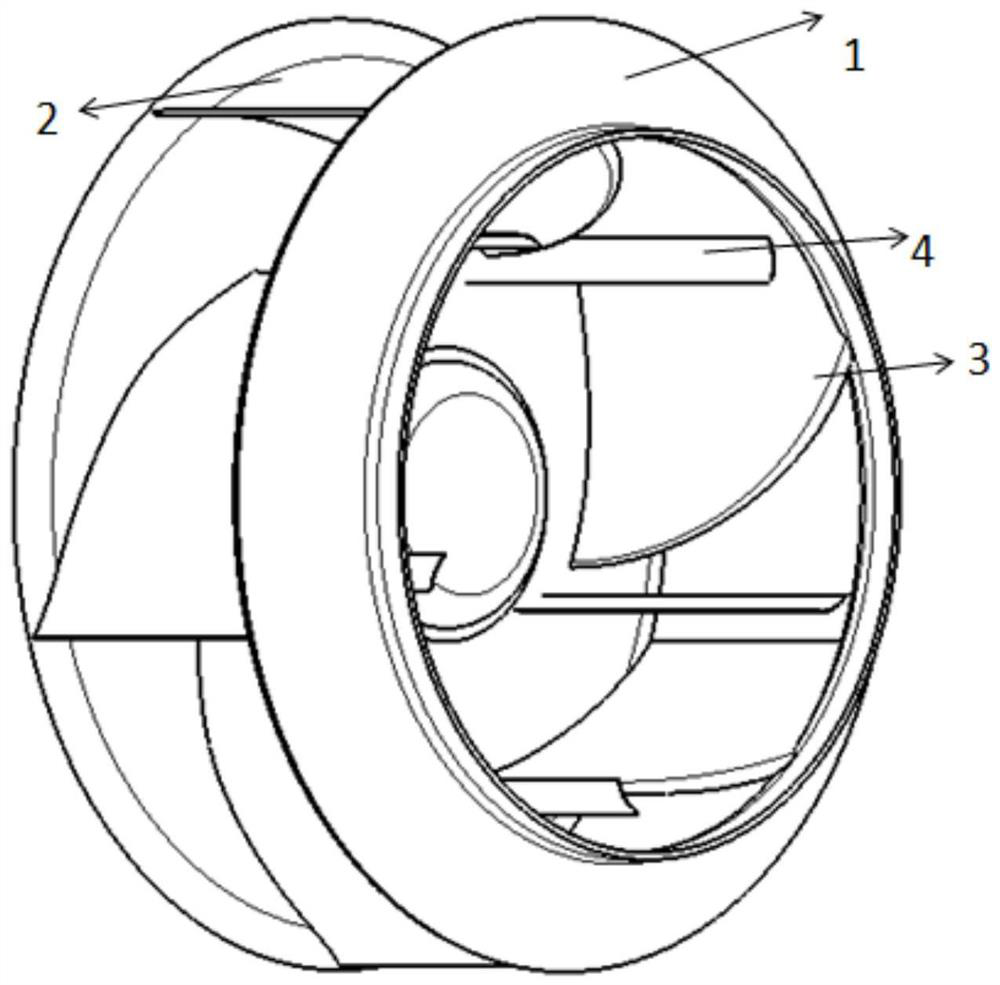
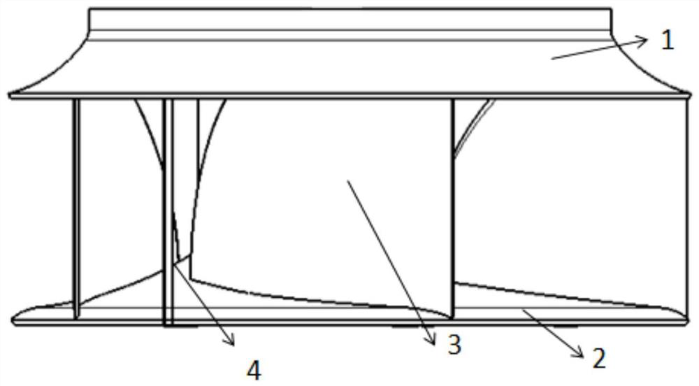
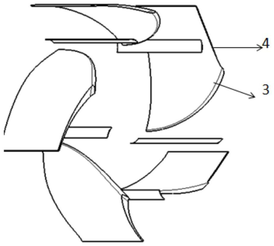
[0024] Please refer to Figure 1 to Figure 4 , figure 1 Schematic diagram of the structure of the centrifugal impeller provided by the present invention; figure 2 is the side view of the centrifugal impeller; i...


PUM


Abstract

The invention discloses a centrifugal impeller, comprising a wheel cover, a wheel disc, and long blades located between the wheel cover and the wheel disc, all the long blades are evenly distributed along the circumferential direction, and any adjacent two long blades are provided with a Small blades at the inlet angle, long blades and small blades have airfoil profiles. In the centrifugal impeller provided by the present invention, there is a blade channel between two adjacent long blades, and the small blade is located in the blade channel. When the air flow enters the blade channel with a relatively large attack angle, the air flow can be adjusted to reduce the impact of the air flow. Angle, so that the inlet airflow of the blade channel becomes more uniform, reducing the impact loss of the blade inlet airflow, the blade shape of the small blade is an airfoil shape, which reduces the separation loss of the suction surface of the blade and reduces the wake loss at the tail of the blade, so as to improve the impeller efficiency and noise reduction purposes.

Description

technical field [0001] The invention relates to the technical field of fluid machinery, in particular to a centrifugal impeller. Background technique [0002] The impeller of the centrifugal fan is its core component, and the blades in the impeller are mostly airfoils. How to improve the flow distribution of gas in the impeller and reduce the noise is the main research direction in this field. The factors affecting the efficiency of the fan and the excessive noise of the fan mainly come from two aspects. One is that during the rotation of the impeller, the pressure of the airflow on the pressure surface of the blade is higher, the pressure of the airflow on the suction surface is lower, and the boundary on the suction surface The thickness of the layer gradually increases from the blade inlet to the outlet. When the kinetic energy of the airflow is insufficient, the separation of the airflow will occur, forming a vortex zone, which affects the efficiency of the centrifugal ...

Claims


Application Information

Patent Timeline
Patent Type & Authority Patents(China)
IPC IPC(8): F04D29/28F04D29/30F04D29/66
CPCF04D29/281F04D29/30F04D29/666
Inventor 李帅领陈宗华
Owner FANS TECH ELECTRIC CO LTD
Learn More