
Ventilation ball base structure corresponding to building heat dissipation cover

A heat dissipation cover, building technology, applied in the direction of space heating and ventilation, heating and ventilation cover/cover, space heating and ventilation details, etc., can solve the problems of laborious and costly

Inactive Publication Date: 2018-12-18
FRADOX GLOBAL CO LTD
View PDF13 Cites 0 Cited by
  • Summary
  • Abstract
  • Description
  • Claims
  • Application Information

AI Technical Summary

Problems solved by technology

However, for those who have already installed ventilation balls, if they want to convert it into a heat dissipation cover, they often have to disassemble the entire set of ventilation balls, and then install a heat dissipation cover, which will take a lot of time and cost.

Method used


Image

  • Ventilation ball base structure corresponding to building heat dissipation cover
  • Ventilation ball base structure corresponding to building heat dissipation cover
  • Ventilation ball base structure corresponding to building heat dissipation cover

Examples


Embodiment Construction

[0024] The structure, features and embodiments of the present invention are described below with the aid of drawings, so that examiners can have a better understanding of the present invention.

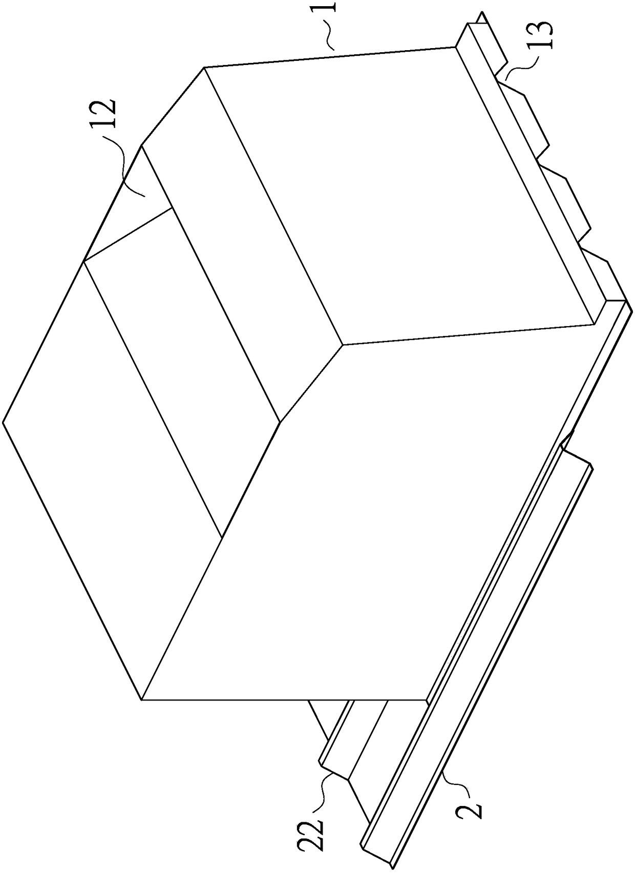
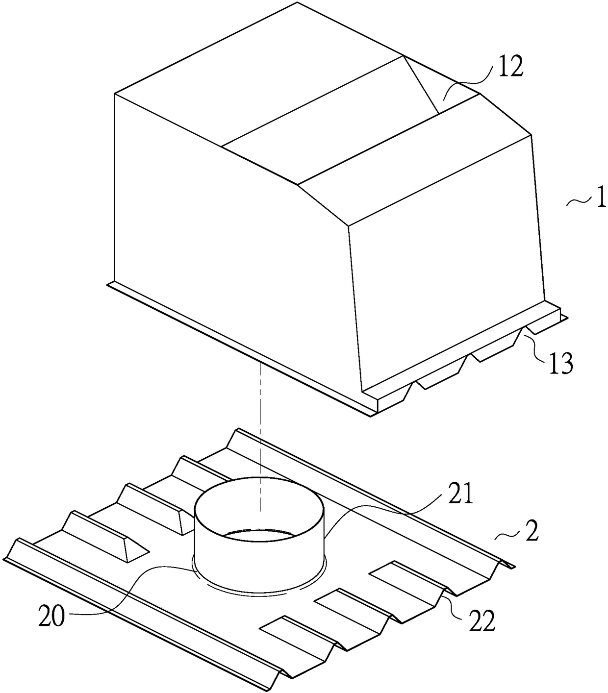
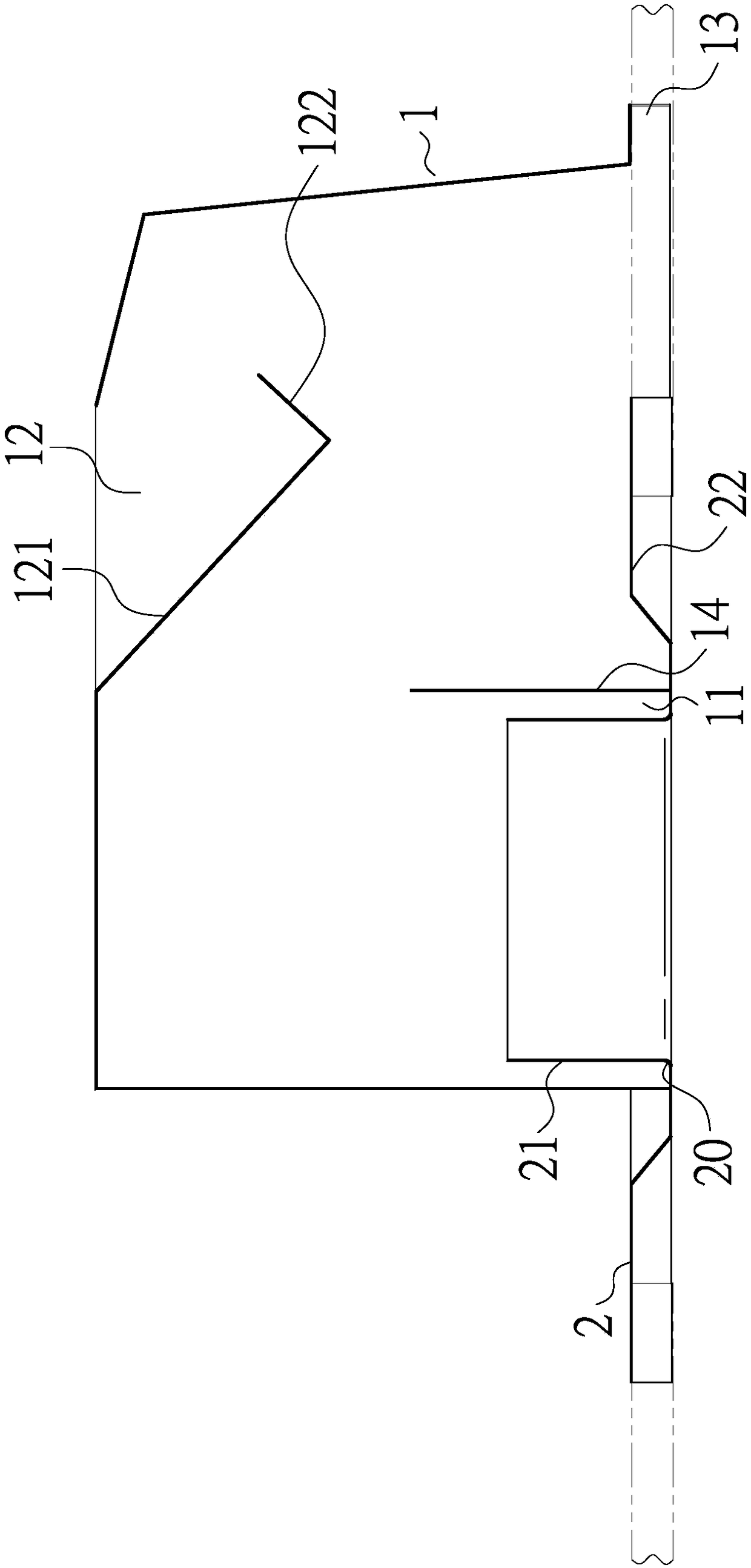
[0025] see figure 1 ,Cooperate figure 2 As shown, the present invention relates to a construction of a building heat dissipation cover corresponding to a ventilation ball base structure, including a heat dissipation cover main body 1, and the heat dissipation cover main body 1 includes an air inlet hole 11 for matching image 3 The air inlet 11 can be framed by the shell wall of the heat dissipation cover main body 1 and a partition plate 14 provided between the two symmetrical shell walls of the heat dissipation cover main body 1, and the heat dissipation cover main body 1 includes an air outlet hole 12 , and the air inlet hole 11 and the air outlet hole 12 form an exhaust path, one side of the air outlet hole 12 extends obliquely downward toward the main body 1 of the heat dissipa...


PUM


Abstract

The invention provides a ventilation ball base structure corresponding to a building heat dissipation cover. A ventilation ball base corresponding to the building heat dissipation cover is effectivelycombined, accordingly, a person using a ventilation ball can detach a body of the ventilation ball, and the ventilation ball base is left for corresponding frame arrangement of a building heat dissipation cover body. Thus, a user adopting the ventilation ball can reduce complexity of complete-set mounting and dismounting.

Description

technical field [0001] The invention relates to building accessories, in particular to a building cooling cover. Background technique [0002] Buildings often have to be ventilated and heat-dissipated due to stuffy heat. If there are only simple heat-dissipating windows or relying on power to extract and exhaust hot air, it is often not enough, especially if steel structure houses, iron houses or simple work houses cannot Without sufficient heat dissipation, it will be more difficult to live or work. [0003] Later, some operators launched the so-called ventilation ball, which rotates the body of the ventilation ball by external wind force, and the indoor hot air can be discharged from the gaps in the blades. However, it is possible that the main body of the ventilation ball does not rotate smoothly because the rotation of the bearing of the ventilation ball is not smooth, or the inclination angle of the ventilation ball is not good, which may cause rainwater to infiltrate ...

Claims


Application Information

Patent Timeline
IPC IPC(8): F24F7/02F24F13/20
CPCF24F7/02F24F13/20F24F2013/205
Inventor 陈忠正
Owner FRADOX GLOBAL CO LTD
Learn More