Kiln cooling wall leakage acquisition unit and device and cooling wall detecting method
A collection unit and detection method technology, applied in the detection field, can solve the problems of cooling wall leakage detection, inconvenience and the like
- Summary
- Abstract
- Description
- Claims
- Application Information
AI Technical Summary
Problems solved by technology
Method used
Image

Examples
Embodiment 1
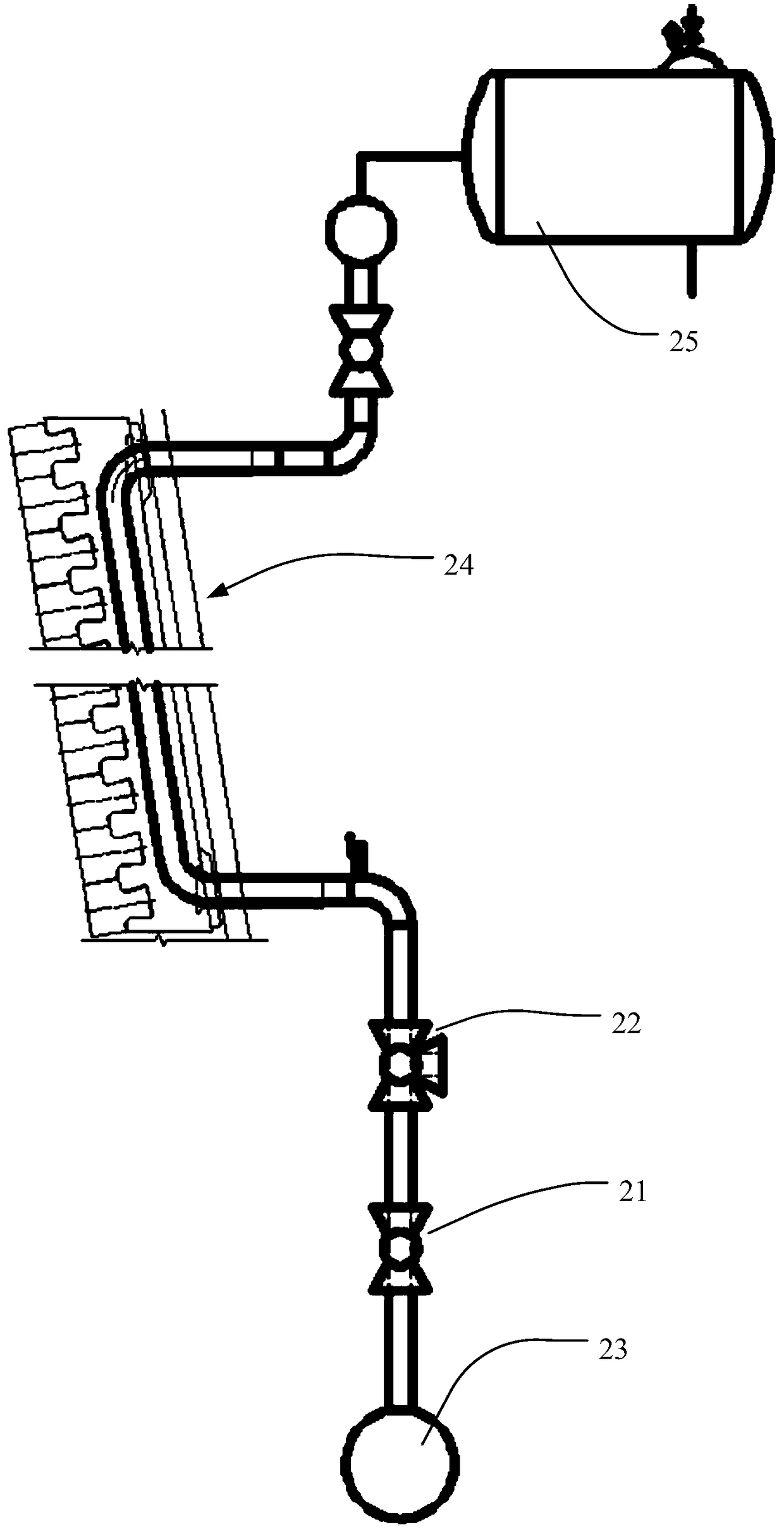
[0052] see figure 2 , the cooling channel at least includes a first valve 21 for opening or closing the cooling channel and a second valve 22 for releasing the leakage collection unit of the kiln stave, the first valve 21 is a two-way valve, The second valve 22 is a three-way valve, and the second valve 22 includes a first port for communicating with the cooling channel, a second port, and a third port for releasing the leakage collection unit of the kiln stave. , specifically, the second valve is a T-shaped three-way valve.
[0053] First close the first valve 21, open the first interface (water inlet) and the second interface (water outlet) of the second valve 22; open the switch of the collection unit, put the collection unit into the third interface, and turn the second valve 22 to connect Pipeline; then open the first valve 21, the water supply pipe 23 provides cooling liquid, under the action of cooling liquid and buoyancy, the collection unit moves along the cooling c...
Embodiment 2
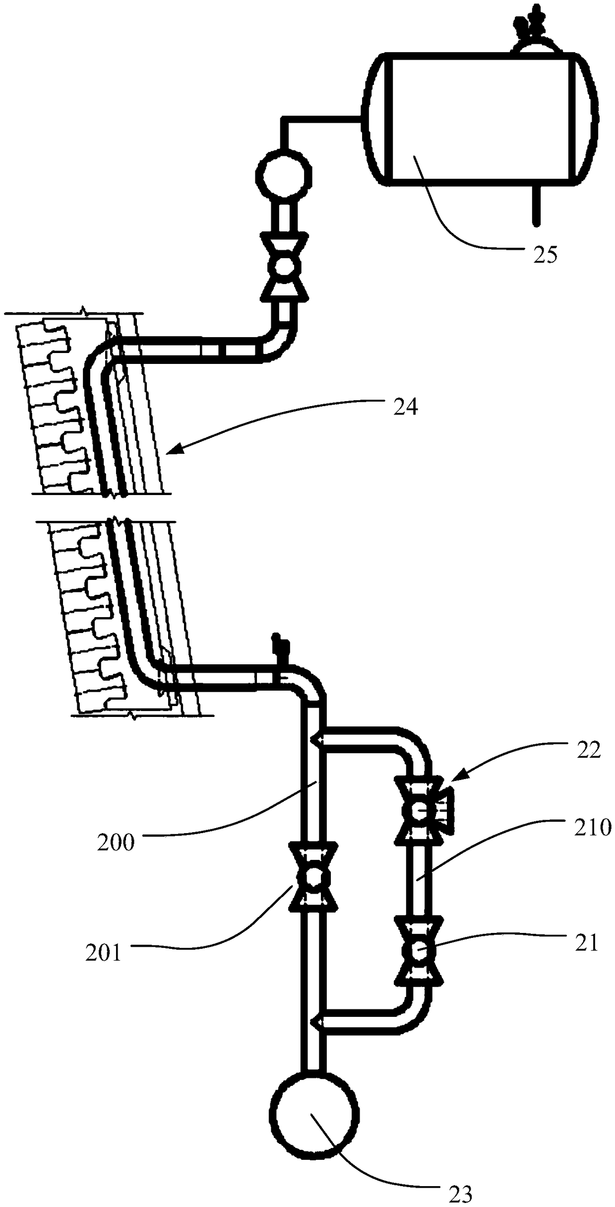
[0055] see image 3 , the cooling channel includes a main channel 200 and a bypass channel 210, the bypass channel 210 is connected in parallel with the main channel 200, and the first valve 21 and The second valve 22 is provided with a switch valve 201 on the main channel 200 .
[0056] First close the first valve 21 of the bypass channel 210, open the first interface (water inlet) and the second interface (water outlet) of the second valve 22; open the collection unit switch, put the collection unit into the third interface, rotate the second The second valve 22 is connected to the pipeline; then the first valve 21 is opened, the on-off valve 201 is closed, the water supply pipe 23 provides cooling liquid, and under the force and buoyancy of the cooling liquid, the collection unit moves along the cooling channel and the direction in which the cooling liquid flows , and finally enter the cooling channel or degassing tank 25 and other devices, and capture the collection unit ...
Embodiment 3
[0058] see Figure 4 , the cooling channel includes a main channel 200, a bypass channel 210 and a branch channel 220, the main channel 200 is connected in parallel with the bypass channel 210, and the bypass channel 210 is provided with at least two of the The first valve 21, the channel between two adjacent first valves 21 is connected in series with the branch channel 220, the second valve 22 is provided on the branch channel, and the switching valve 201 is provided on the main channel.
[0059] First close the two first valves 21 of the bypass passage 210, open the second valve 22; open the collection unit switch, put the collection unit into the branch passage 220; close the second valve 22, open the two valves of the bypass passage 210 The first valve 21 closes the on-off valve 201 on the main channel 200. Under the force and buoyancy of the cooling liquid, the collection unit moves along the cooling channel and the direction in which the cooling liquid flows, and finall...
PUM
 Abstract
Description
Claims
Application Information
 - R&D
- Intellectual Property
- Life Sciences
- Materials
- Tech Scout
- Unparalleled Data Quality
- Higher Quality Content
- 60% Fewer Hallucinations
Browse by: Latest US Patents, China's latest patents, Technical Efficacy Thesaurus, Application Domain, Technology Topic, Popular Technical Reports.
© 2025 PatSnap. All rights reserved.Legal|Privacy policy|Modern Slavery Act Transparency Statement|Sitemap|About US| Contact US: help@patsnap.com