CO2 Compression and Delivery Systems

A carbon dioxide, delivery system technology, applied in the direction of pressure vessels, equipment discharged from pressure vessels, methods of container discharge, etc., can solve the problems of carbon dioxide storage and liquefaction without consideration

Active Publication Date: 2021-11-30
SAES PURE GAS
View PDF25 Cites 0 Cited by
  • Summary
  • Abstract
  • Description
  • Claims
  • Application Information

AI Technical Summary

Problems solved by technology

However, this patent does not consider the storage and liquefaction of carbon dioxide, and the system described therein envisages the use of complex structures comprising a plurality of generally defined annular concentric channels

Method used


Image

  • CO2 Compression and Delivery Systems
  • CO2 Compression and Delivery Systems
  • CO2 Compression and Delivery Systems

Examples


Embodiment Construction

[0020] It has been surprisingly found that a carbon dioxide compression and delivery system having a carbon dioxide flow channel width comprised between 1mm and 10mm and using multiple reversible thermoelectric devices, technical information and teaching not disclosed in any of the above referenced prior art by thermoelectric effect with CO 2 Technical issues of management (compression and delivery) are particularly relevant.

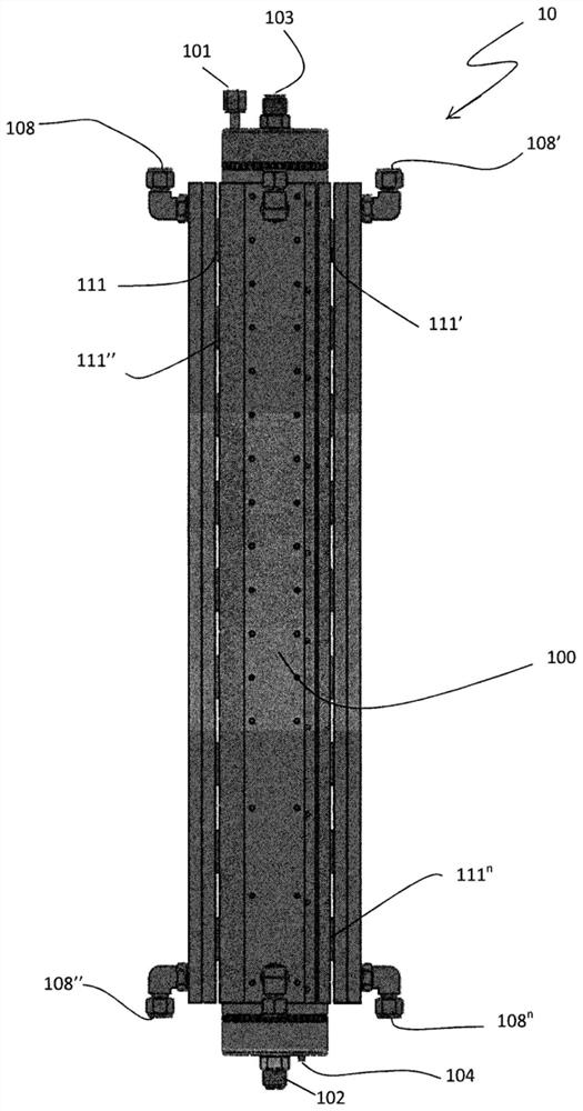
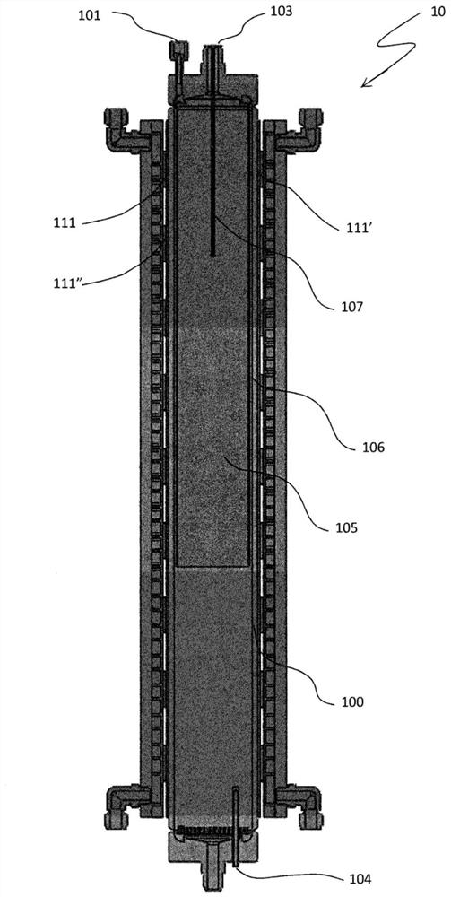
[0021] In the inventive concept of the present invention, substantially the entire length of the system vessel contributes to cooling (for CO2 compression) and heating (for CO2 delivery), which means that the thermoelectric devices are ideally evenly distributed over the length of the vessel superior. In the smallest configuration, this translates into the use of three thermoelectric devices positioned corresponding to the lower, middle and upper sections of the carbon dioxide compression and delivery system vessel. This ensures more efficient storage...


PUM

PropertyMeasurementUnit
widthaaaaaaaaaa
lengthaaaaaaaaaa

Abstract

The present invention provides carbon dioxide compression and delivery devices using multiple reversible thermoelectric devices and methods of operating such carbon dioxide compression and delivery devices.

Description

Background technique [0001] carbon dioxide (CO 2 ) compression and conveying systems can be used in many industrial applications, for example, a fairly common use is for the cleaning of semiconductors. For this application, flow, delivery characteristics and gas quality (especially with regard to contaminants) are critical. [0002] Carbon dioxide substrate cleaning is described in US Patent 5,125,979 to Swain et al., in which small carbon dioxide particles condense into large snowflakes. More specifically, Swain et al. describe a cleaning process that involves diffusing carbon dioxide from an orifice into an insulated chamber to form small carbon dioxide particles, retaining the small carbon dioxide particles in the isolated chamber until small carbon dioxide Until the particles condense into large snowflakes, the large snowflakes are sandwiched in a high-speed vortex of inert gas to accelerate the large snowflakes, and the flow of inert gas and the accelerated large snowfl...

Claims


Application Information

Patent Timeline
Patent Type & Authority Patents(China)
IPC IPC(8): F17C7/02H01L21/02B24C1/00B24C3/32
CPCB24C1/00B24C3/32F17C2227/0376B24C1/003B24C3/322F17C2227/047F17C2227/0107F17C2227/0304F17C2227/0379F17C2221/013F17C7/04F17C7/02
Inventor 查尔斯·阿普尔加思马修·布鲁宁
Owner SAES PURE GAS
Why Eureka
Try Eureka