Industrial adsorbent equipment

An adsorbent and equipment technology, applied in the field of industrial adsorbent equipment, can solve the problems of low mixing efficiency and complicated operation steps, and achieve the effect of reducing working time and improving mixing efficiency.

Inactive Publication Date: 2018-12-25
广州上同环保科技有限公司
View PDF0 Cites 0 Cited by
  • Summary
  • Abstract
  • Description
  • Claims
  • Application Information

AI Technical Summary

Problems solved by technology

[0002] At present, in the process of preparing activated carbon, it is necessary to mix and stir the raw materials for its preparation. The current mixing equipment us

Method used


Image

  • Industrial adsorbent equipment
  • Industrial adsorbent equipment

Examples


Embodiment Construction

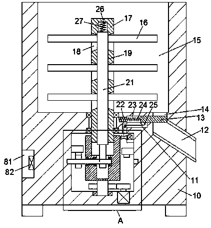
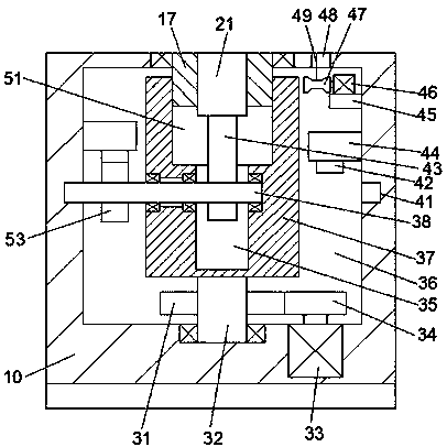
[0012] Combine below Figure 1-2 The present invention will be described in detail.

[0013] refer to Figure 1-2 , an industrial adsorbent device according to an embodiment of the present invention, comprising a main frame body 10, a mixing chamber 15 is arranged in the top end surface of the main frame body 10, and the main frame body 10 on the lower side of the mixing chamber 15 A circular drive chamber 36 is provided inside, and a mixing shaft 17 is installed in rotational cooperation between the circular drive chamber 36 and the mixing chamber 15. The mixing shaft 17 extends into the mixing chamber 15 and the bottom end surface is up and down. A shrinking groove 19 is extended, and a shrinking arm 21 is installed slidingly in the shrinking groove 19. A plurality of groups of openings 18 are arranged symmetrically on the left and right sides of the shrinking groove 19, and a mixing blade 16 is installed in the opening 18 in a sliding fit. The mixing vane 16 extends into ...


PUM


Abstract

The invention discloses industrial adsorbent equipment. The industrial adsorbent equipment comprises a main frame, a mixing cavity is arranged in the to end face of the main frame, a circular drive chamber is arranged in the main frame on the lower side of the mixing cavity, a mixing shaft is rotatably and fittingly mounted between the circular drive chamber and the mixing cavity, the mixing shaftextends to the mixing cavity to be provided with a telescopic groove extending up and down in the bottom end face of the mixing shaft, a telescopic arm is slidably and fittingly mounted in the telescopic groove, multiple sets of opening cavities are symmetrically arranged on left and right sides of the telescopic groove, mixing blades are slidably and fittingly mounted in the opening cavities andextend to the mixing cavity to be fixedly connected with the telescopic arm, a sinking cavity is arranged in the top wall of the telescopic groove, a first elastic piece is fittingly mounted betweenthe top wall of the sinking cavity and the top end face of the telescopic arm in a pressing manner, and the mixing shaft extends to the circular drive cavity to be provided with a steering table on the outer periphery.

Description

technical field [0001] The invention relates to the technical field of activated carbon, in particular to an industrial adsorbent device. Background technique [0002] At present, in the process of preparing activated carbon, it is necessary to mix and stir the raw materials for its preparation. The current mixing equipment usually only uses mixing blades to rotate and mix the materials. The mixing efficiency is low and the operation steps are cumbersome. Therefore, it needs to be improved. Contents of the invention [0003] The object of the present invention is to provide an industrial adsorbent device for overcoming the above-mentioned defects in the prior art. [0004] An industrial adsorbent device according to the present invention comprises a main frame body, a mixing chamber is arranged in the top end surface of the main frame body, and a circular drive chamber is arranged in the main frame body on the lower side of the mixing chamber, and the A mixing shaft is in...

Claims


Application Information

Patent Timeline
IPC IPC(8): B01F11/00B01F15/02B01J20/20B01J20/30
CPCB01J20/20B01J20/30B01F31/44B01F35/754
Inventor 莫洁琼
Owner 广州上同环保科技有限公司
Why Eureka
Try Eureka