
Device used for printing and machining materials

A technology for processing materials and shells, applied in the field of 3D printing materials, can solve the problems of low mixing efficiency and cumbersome operation steps, so as to reduce the working time, solve the insufficient mixing efficiency, and improve the mixing efficiency.

Inactive Publication Date: 2019-02-01
广州纶镁数据系统有限公司
View PDF0 Cites 0 Cited by
  • Summary
  • Abstract
  • Description
  • Claims
  • Application Information

AI Technical Summary

Problems solved by technology

[0002] At present, in the preparation process of 3D printing materials, it is necessary to mix and stir the raw materials for its preparation. The current mixing equipment usually only rotates and mixes the materials by rotating the blades. The mixing efficiency is low and the operation steps are cumbersome. Therefore, needs improvement

Method used


Image

  • Device used for printing and machining materials
  • Device used for printing and machining materials

Examples


Embodiment Construction

[0012] Combine below Figure 1-2 The present invention will be described in detail.

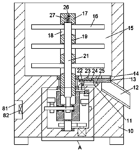
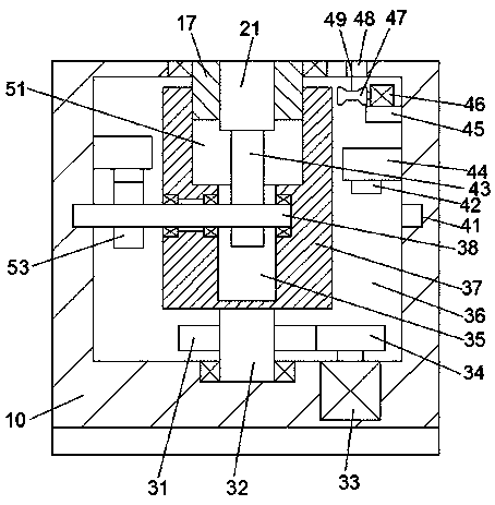
[0013] refer to Figure 1-2 According to an embodiment of the present invention, a device for printing processing materials includes a housing 10, a mixing chamber 15 is provided in the top end surface of the housing 10, and a mixing chamber 15 is provided in the housing 10 on the lower side of the mixing chamber 15. There is an annulus driving chamber 36, and a mixing shaft 17 is installed in rotation cooperation between the annulus driving chamber 36 and the mixing chamber 15, and the mixing shaft 17 extends into the mixing chamber 15 and the bottom end surface A retractable chamber 19 extends up and down inside the retractable chamber 19, and a retractable arm 21 is installed slidingly in the retractable chamber 19. The left and right sides of the retractable chamber 19 are symmetrically provided with a plurality of groups of openings 18, and the openings 18 A rotating blade 16 is instal...


PUM


Abstract

The invention discloses a device used for printing and machining materials. The device comprises a shell. An evenly-mixing cavity is formed in the end face of the top of the shell. A ring face drive cavity is formed in the portion, located on the lower side of the evenly-mixing cavity, of the shell. An evenly-mixing shaft is installed between the ring face drive cavity and the evenly-mixing cavityin a rotary fitting manner. The evenly-mixing shaft extends into the evenly-mixing cavity, and a storing cavity is formed in the end face of the bottom in an up and down extending manner. A storing arm is installed in the storing cavity in a sliding fitting manner. Multiple holes are symmetrically formed in the left side and the right side of the storing cavity. A rotating blade is installed in each hole in a sliding fitting manner. The rotating blades extend into the evenly-mixing cavity and is fixedly connected with the storing arm. A concave cavity is formed in the top wall of the storingcavity. A first pressing spring is installed between the top wall of the concave cavity and the end face of the top of the storing arm in an ejecting fitting manner. The evenly-mixing shaft extends into the ring face drive cavity, and the periphery of the evenly-mixing shaft is fixedlyprovided with a rotary connecting table.

Description

technical field [0001] The invention relates to the technical field of 3D printing materials, in particular to a device for printing processing materials. Background technique [0002] At present, in the preparation process of 3D printing materials, it is necessary to mix and stir the raw materials for its preparation. The current mixing equipment usually only rotates and mixes the materials by rotating the blade. The mixing efficiency is low and the operation steps are cumbersome. Therefore, needs improvement. Contents of the invention [0003] The object of the present invention is to provide a device for printing processing materials to overcome the above-mentioned defects in the prior art. [0004] A device for printing and processing materials according to the present invention includes a housing, a mixing chamber is provided on the top end surface of the housing, and a ring drive chamber is provided in the housing below the mixing chamber. A mixing shaft is install...

Claims


Application Information

Patent Timeline
Patent Type & Authority Applications(China)
IPC IPC(8): B29B7/08B29B7/16B29B7/22B29B7/26B33Y70/00
CPCB29B7/08B29B7/16B29B7/22B29B7/266B33Y70/00
Inventor 韦健敏
Owner 广州纶镁数据系统有限公司
Learn More