A robot control system

A control system and robot technology, applied in the field of robots, can solve problems such as affecting the service life, affecting the use of robots, unexpected power failure, etc., to achieve the effect of easy power-on use

Inactive Publication Date: 2018-12-25
广州星引科技有限公司
View PDF2 Cites 0 Cited by
  • Summary
  • Abstract
  • Description
  • Claims
  • Application Information

AI Technical Summary

Problems solved by technology

[0002] When the current robot is powered on, the plug needs to be inserted and installed on the power transmission base. The plug and the power transmission base are usually connected by friction fit. When the plug is accidentally touched, the plug is easy to fall off from the power transm...

Method used


Image

  • A robot control system
  • A robot control system
  • A robot control system

Examples


Embodiment Construction

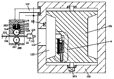
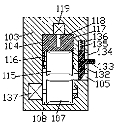
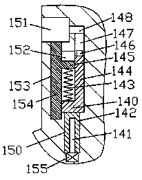
[0015] Combine below Figure 1-3 The present invention will be described in detail.

[0016] refer to Figure 1-3 , a robot control system according to an embodiment of the present invention, including a base 100 and an end portion 114 used in conjunction with the base 100, an opening 113 is provided in the left end surface of the base 100, and the opening The inner wall on the right side of 113 is communicated with a rotating cavity 122, and a winding frame 101 is installed in rotation in the rotating cavity 122. The winding frame 101 is provided with a power connection mechanism 101, and the base on the upper side of the opening cavity 113 A connecting rod 102 is mounted on the left end surface of the seat 100 in rotation. The bottom end of the connecting rod 102 is fixed with a fixed block 103. The front end surface of the fixed block 103 is provided with a wire passage cavity 105 on the left and right. The wire passage chamber A first sliding chamber 136 extends up and d...


PUM


Abstract

A robot control system includes a base and an end head for use with the base, a cavity is arranged in the left end face of the base, a rotary cavity communicates with the inner wall of the right sideof the cavity, a bobbin is rotatably fitted and installed in the rotating cavity, a power connection mechanism is arranged in the bobbin, a connecting rod is rotatably fitted to the left end surface of that base on the upper side of the cavity, a fixing block is fixedly arranged at the bottom tail end of the connecting rod, a left and right penetrating line passing cavity is arranged in the frontside end face of the fixing block, a first sliding cavity is arranged in the top wall of the line passing cavity and extends upward and downward,a baffle plate is slidably fitted and installed in thefirst sliding cavity, a first spring is installed between the top end of the baffle plate and the top wall of the first sliding cavity through press fit, a second sliding cavity penetrating the frontend surface of the fixing block is arranged in the right inner wall of the first sliding cavity, and a push handle fixedly connected with the baffle plate is slidably fitted in the second sliding cavity.

Description

technical field [0001] The invention relates to the technical field of robots, in particular to a robot control system. Background technique [0002] When the current robot is powered on, the plug needs to be inserted and installed on the power transmission base. The plug and the power transmission base are usually connected by friction fit. When the plug is accidentally touched, the plug is easy to fall off from the power transmission base, resulting in Unexpected power failure affects the use of the robot. Moreover, the length of the cable that is often connected to the robot is difficult to adjust, and it is often dragged on the ground, which is easy to be contaminated with dust and affects the service life. Contents of the invention [0003] The object of the present invention is to provide a robot control system for overcoming the above-mentioned defects in the prior art. [0004] According to a robot control system of the present invention, it includes a base and an...

Claims


Application Information

Patent Timeline
IPC IPC(8): H01R13/639H01R13/71H01R13/72H01R13/633
CPCH01R13/639H01R13/633H01R13/71H01R13/72
Inventor 陆伟城
Owner 广州星引科技有限公司
Why Eureka
Try Eureka