
Control method and clamping device for automatic clamping

A control method and clamping device technology, applied in the direction of measuring devices, circuit devices, optical devices, etc., can solve the problems that the timing time cannot be set too long, the space is small, and the use requirements of different groups of people cannot be met.

Active Publication Date: 2021-06-22
SHENZHEN SHENGYAN TECH CO LTD
View PDF5 Cites 0 Cited by
  • Summary
  • Abstract
  • Description
  • Claims
  • Application Information

AI Technical Summary

Problems solved by technology

[0004] 1. The current design only detects the distance of the mobile phone, but does not detect the approaching speed and direction of movement of the mobile phone. Because of the relatively small space in some cars, it is easy to regard the object passing in front of the product as a mobile phone, which causes a mistake. operate
[0005] 2. The current design clamps the mobile phone by timing clamping after opening. If the timing time is set too short, some slow-moving people will not have time to put the mobile phone away; but the timing time cannot be set too long, too long The timing time will make some people who are in a hurry and want to put it away quickly, which cannot meet the requirements of different groups of people.

Method used


Image

  • Control method and clamping device for automatic clamping
  • Control method and clamping device for automatic clamping
  • Control method and clamping device for automatic clamping

Examples


Embodiment Construction

[0041] In order to make the object, technical solution and advantages of the present invention clearer, the present invention will be further described in detail below in conjunction with the accompanying drawings and embodiments. It should be understood that the specific embodiments described here are only used to explain the present invention, not to limit the present invention.

[0042] In describing the present invention, it should be understood that the terms "length", "width", "upper", "lower", "front", "rear", "left", "right", "vertical", The orientation or positional relationship indicated by "horizontal", "top", "bottom", "inner", "outer", etc. are based on the orientation or positional relationship shown in the drawings, and are only for the convenience of describing the present invention and simplifying the description, rather than Nothing indicating or implying that a referenced device or element must have a particular orientation, be constructed, and operate in a ...


PUM


Abstract

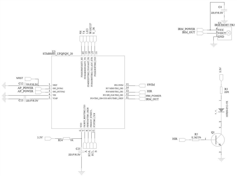
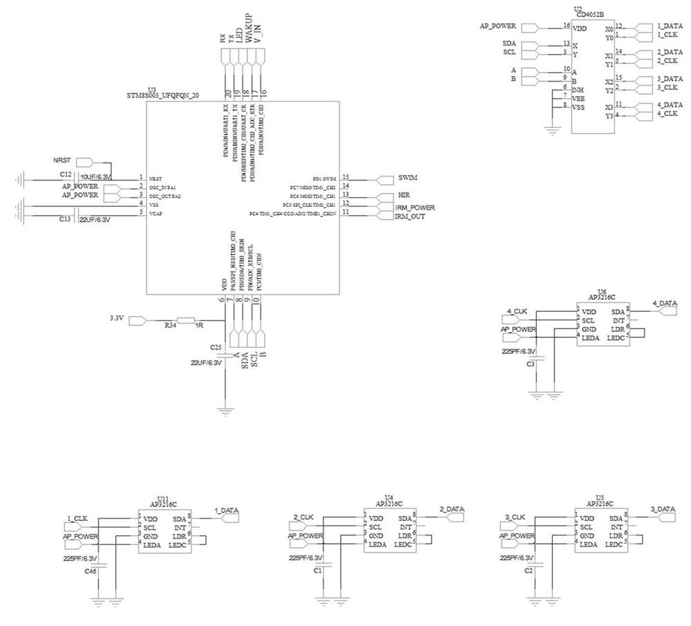
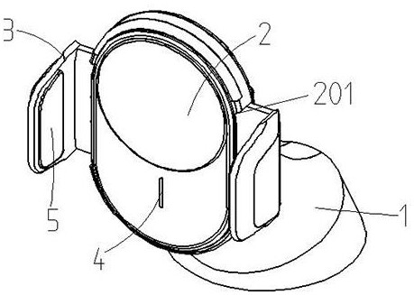
The invention relates to a control method and a clamping device for automatic clamping and placing. The control method for automatic clamping and placing is used for a mobile phone charging bracket, specifically as follows: the first sensor obtains the moving state of the first object, and the control circuit according to the moving state of the first object Calculate the moving speed and compare it with the set speed range to determine whether the first object is to be charged; if it is judged that the object is to be charged, the control circuit controls the clamping structure to open, otherwise the clamping structure does not move; when the second sensor learns After the object approaches to a certain distance, the control circuit controls the clamping structure to start clamping until the clamping structure clamps the electronic product. The clamping device for automatic clamping is characterized in that it includes a control circuit, a first sensor, a second sensor and a clamping structure. The invention judges the user's insertion intention through multiple detections by the first sensor and calculates the direction and speed of the mobile phone's movement, thereby solving the problem that the existing mobile phone holder is easy to misuse.

Description

technical field [0001] The invention relates to the technical field of automatic clamping, relates to the clamping and releasing of a charger, and relates to a control method and a clamping device for automatic clamping and releasing. Background technique [0002] The existing automatic clamping mobile phone charging bracket installs a sensor directly in front to detect whether the mobile phone is approaching. When it detects that a mobile phone is approaching, it will drive the internal structure to drive the left and right clamping pieces to open, and then wait for a certain period of time. After a period of time, the left and right clamping pieces are electrically driven again to clamp the mobile phone. [0003] But when the user needs to take off the mobile phone, the user needs to touch the touch switch on one side of the product. When the internal circuit detects that the touch switch is triggered, the left and right clamping pieces are opened by electric drive, and th...

Claims


Application Information

Patent Timeline
Patent Type & Authority Patents(China)
IPC IPC(8): H02J7/00H04M1/04G01B11/00
CPCG01B11/00H02J7/0044H02J7/007H04M1/04
Inventor 张戟
Owner SHENZHEN SHENGYAN TECH CO LTD
Learn More