Resistance strain gauge pasting device

A technology of resistance strain gauges and strain gauges, which is applied in the direction of instruments, measuring devices, and material gluing, can solve the problems of strain gauge displacement, low efficiency, and poor working environment, and achieve the effect of improving efficiency and working environment

Pending Publication Date: 2019-04-16
CENT SOUTH UNIV
View PDF0 Cites 0 Cited by
  • Summary
  • Abstract
  • Description
  • Claims
  • Application Information

AI Technical Summary

Problems solved by technology

Because the epoxy resin is in the form of paste, the strain gauges are not easy to stick flat. When pasting the vertical plane strain gauges, due to the slow curing of the epoxy resin, the strain gauges are prone to misalignment and deviate from the original position. Similarly, the lower plane cannot Paste the strain gauge
Paste the strain gauges in the traditional way. After the strain gauges are pasted, then paste the terminals. Since the curing time of the epoxy resin takes one day, or even more than one day, the efficiency of pasting the strain gauges in the traditional way is low, and the pasting materials are easy to get on hand. The working environment is relatively poor. poor, very inefficient

Method used


Image

  • Resistance strain gauge pasting device
  • Resistance strain gauge pasting device
  • Resistance strain gauge pasting device

Examples


Embodiment Construction

[0023] In order to better understand the present invention, the invention will be described in further detail below in conjunction with the accompanying drawings and implementation examples, but the embodiments of the present invention are not limited thereto, and the scope of protection of the present invention also relates to those skilled in the art who can achieve according to the concept of the present invention. Think of the equivalent technical means.

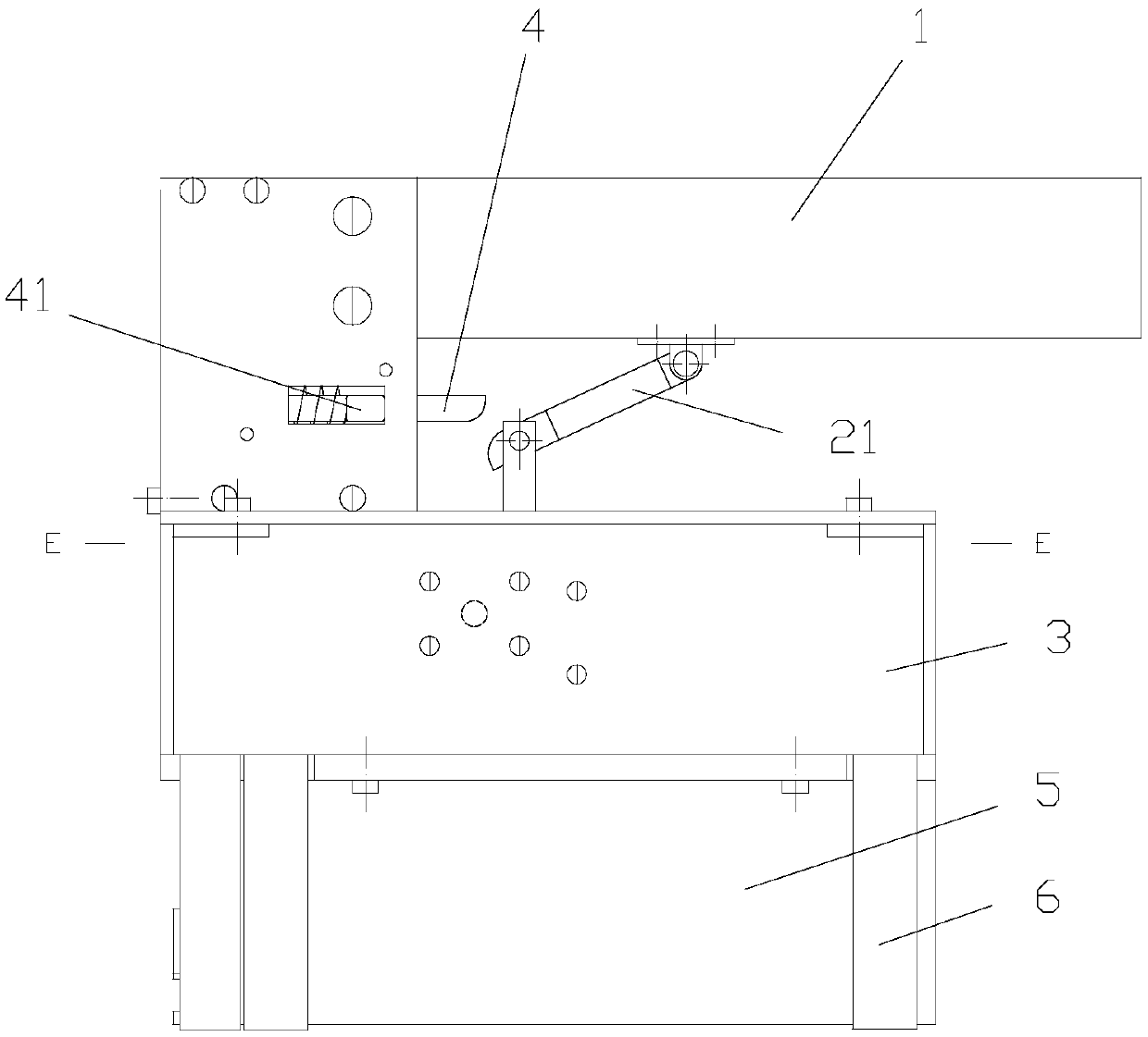
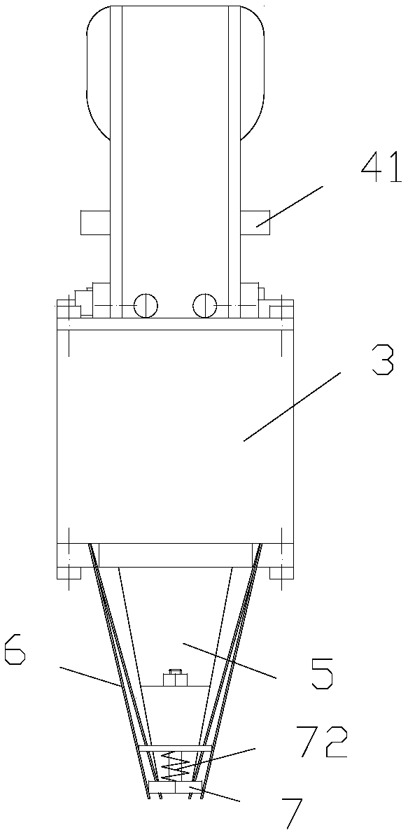
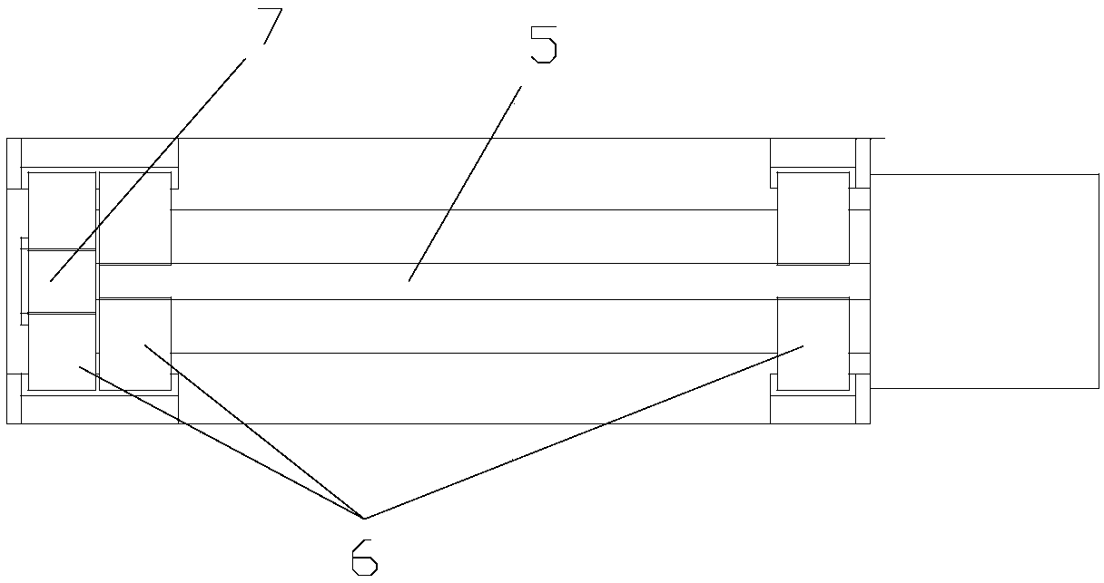
[0024] Such as Figures 1 to 6 As shown, a resistance strain gauge sticking device includes an inverted trapezoidal indenter 5, the end of the indenter 5 is provided with a scale that is convenient for aligning with the midline when the strain gauge is pasted, and the bottom surface of the indenter 5 is in line with the A plane matching the size of the strain gauge to be pasted, the indenter 5 cuts off a part of the upper and lower parts corresponding to the connection terminal of the strain gauge to be pasted, thereby f...


PUM


Abstract

The invention discloses a resistance strain gauge pasting device. The resistance strain gauge pasting device comprises a pressing head, the bottom surface of the pressing head is a plane matched withthe size of a to-be-pasted strain gauge, a bracket is fixedly arranged on the pressing head, and a handle used for conveniently lifting the pressing head is fixedly arranged on the bracket; and a transmission plate is arranged on the top surface of the pressing head, a linear motion device driving the transmission plate to move up and down is arranged on the transmission plate, a plurality of supporting sheets are arranged on the two sides of the pressing head and the positions, closely attached to the pressing head, at the initial and tail ends at least in the length direction of the to-be-pasted strain gauge, the upper ends of the supporting sheets are fixed on the transmission plate and in linkage with the transmission plate, and a fixture capable of clamping the to-be-pasted strain gauge is arranged at the positions, stretched out of the bottom surface of the pressing head in the initial state, corresponding to the lower ends of the supporting sheets. The resistance strain gauge pasting device effectively solves the problems that the strain gauge pasting is easy to stagger and deviate from the original position, and the paste material is easy to stick to the hands and affects the paste efficiency, the efficiency of the strain gauge pasting is improved, the working environment is improved, and meanwhile, pasting of any position plane can be achieved.

Description

technical field [0001] The invention relates to a sticking device for resistance strain gauges. Background technique [0002] The resistance strain gauge is composed of sensitive grid, substrate, covering layer and lead-out wire. The lead-out wire is welded on the terminal, and the terminal is connected to the wire. The strain gauge is pasted on the test piece and connected to the strain gauge through the wire. The principle of the current-carrying bridge is connected into different bridge circuits, and the output resistance change rate of the Wheatstone bridge is converted into strain through the strain gauge, and the stress of the sticking position of the strain gauge on the test piece can be calculated through the strain measurement, so as to judge the force of the test piece Therefore, the pasting of strain gauges is an important technical means for engineering testing and scientific research, and the quality of strain gauge pasting directly affects the test results. Th...

Claims


Application Information

Patent Timeline
IPC IPC(8): F16B11/00G01L1/22
CPCF16B11/006G01L1/22
Inventor 邹建林松王晓光
Owner CENT SOUTH UNIV
Why Eureka
Try Eureka