[0023] In order to make the purposes, technical solutions and advantages of the embodiments of the present invention clearer, the technical solutions in the embodiments of the present invention will be clearly and completely described below with reference to the accompanying drawings in the embodiments of the present invention. Obviously, the described embodiments These are some embodiments of the present invention, but not all embodiments.
[0024] Based on the embodiments of the present invention, all other embodiments obtained by those of ordinary skill in the art without creative efforts shall fall within the protection scope of the present invention. The embodiments described below and features in the embodiments may be combined with each other without conflict.
[0025] Among them, terms such as "upper" and "lower" are used to describe the relative positional relationship of each structure in the accompanying drawings, which are only for the convenience of description and clarity, and are not used to limit the scope of implementation of the present invention. Changes or adjustments made without substantial changes to the technical content shall also be regarded as the scope of the present invention.
[0026] It should be noted that, in the description of the present invention, the terms "first" and "second" are only used to facilitate the description of different components, and should not be construed as indicating or implying a sequence relationship, relative importance, or implicitly indicating indicated the number of technical characteristics. Thus, a feature delimited with "first", "second" may expressly or implicitly include at least one of that feature.
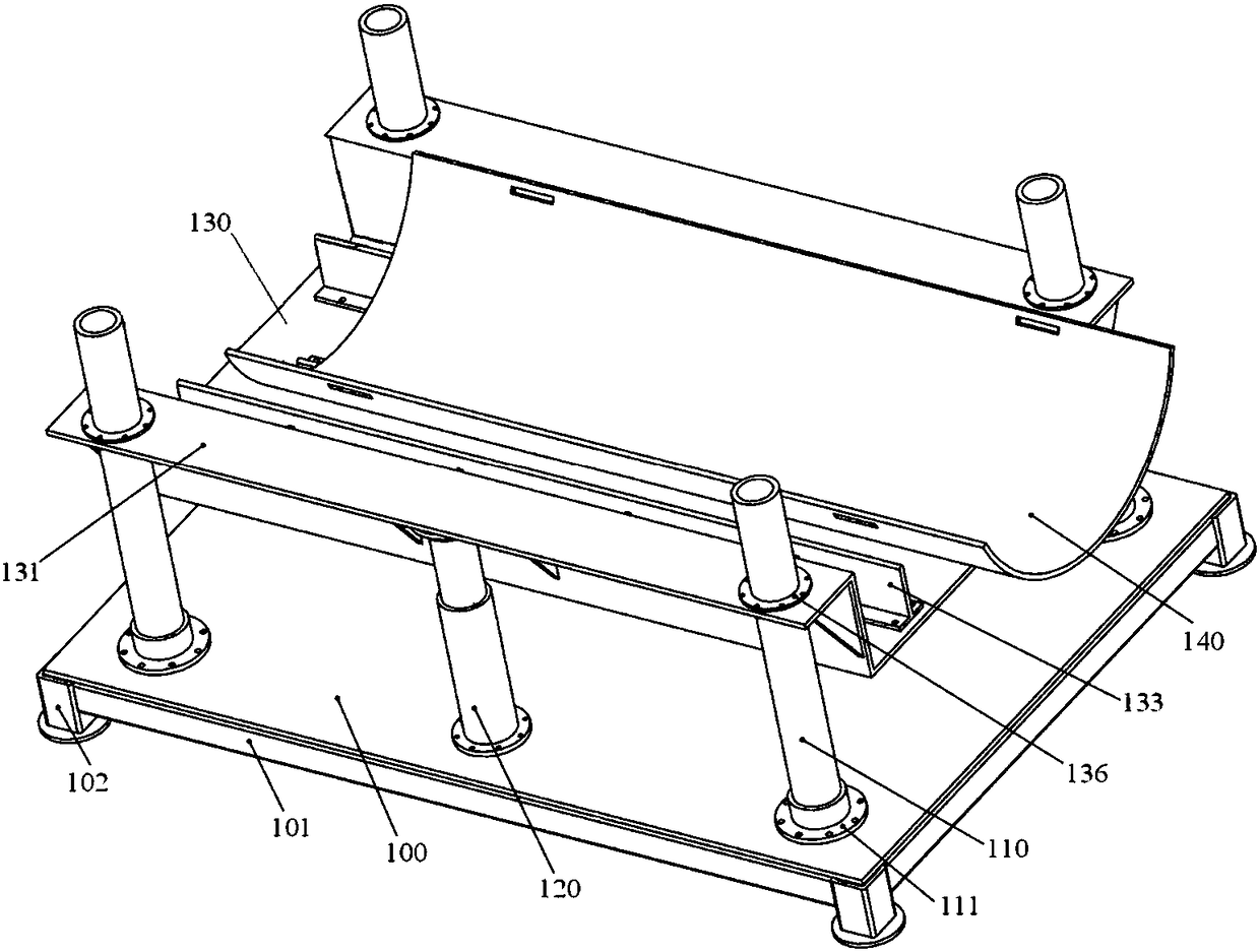
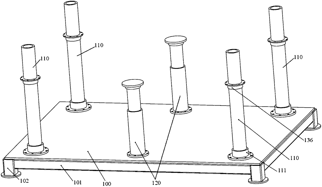
[0027] figure 1 It is a schematic structural diagram of an embodiment of the pig service device of the present invention; figure 2 It is a schematic structural diagram of the base, the bottom plate, the upright column and the supporting oil cylinder in the pig launching device according to the embodiment of the present invention.
[0028] Please refer to Figure 1-2 , the present embodiment provides a pig ball service device, including: a bottom plate 100, at least two uprights 110 and at least two supporting cylinders 120 are arranged on the bottom plate 100; It is also slidably connected with the upright column 110; the support frame 130 is provided with an arc-shaped sliding plate 140, and the sliding plate 140 is used to support the pig.
[0029] Wherein, at least two uprights 110 are symmetrically distributed on both sides of the support frame 130 , and at least two support cylinders 120 are symmetrically distributed on both sides of the support frame 130 to more reliably support the support frame 130 and keep the support frame 130 stable.
[0030] Specifically, the bottom plate 100 is a rectangular steel plate with a certain rigidity, so as to be able to bear a certain weight. Each support oil cylinder 120 is evenly distributed on the bottom plate 100, the lower end of the cylinder body of the support oil cylinder 120 is provided with a flange plate, and screw holes are provided on the flange plate and the bottom plate 100, so as to connect the flange plate and the bottom plate by screws, bolts, etc. 100 screw connections. The upper end of the plunger of the support oil cylinder 120 bears against the support frame 130 so as to be able to drive the support frame 130 to move up and down, that is, to drive the support frame 130 to move up and down.
[0031] The uprights 110 are evenly distributed on the bottom plate 100, and the uprights 110 can also be screwed to the bottom plate 100. Specifically, the uprights 110 are inserted into the central hole of the support 111, and the lower end of the support 111 is provided with a flange. It is screwed to the base plate 100. Of course, the upright column 110 and the cylinder body supporting the oil cylinder 120 can also be fixed by welding with the bottom plate 100 . The cross-section of the upright column 110 may be circular, rectangular, or oval, etc. This embodiment does not specifically limit this, and those skilled in the art can set it according to actual needs. The support frame 130 can be sleeved on the upright post 110 so that the support frame 130 can slide relative to the upright post 110 ; wherein, the upright post 110 plays a guiding and limiting role for the support frame 130 to prevent the support frame 130 from being relative to the support cylinder 120 during the operation. Relative movement occurs, helping to ensure that the pig is transported smoothly.
[0032] For example: when the bottom plate 100 is rectangular, four uprights 110 are arranged on the bottom plate 100, and the uprights 110 are respectively located at four corners of the bottom plate 100; two supporting oil cylinders 120 are arranged on the bottom plate 100, and the two supporting oil cylinders 120 and On both sides of the middle of the bottom plate 100 ; wherein, the support cylinders 120 and the uprights 110 on the same side are arranged linearly.
[0033] Since there is a certain distance between the teeing device and the teeing cylinder, in order to ensure the pig is transported smoothly, the sliding plate 140 is only placed on the supporting frame 130, so that under the action of external force, the sliding plate 140 can slide relative to the supporting frame 130, thereby , so that the sliding plate 140 can move and enter a preset distance into the ball cylinder. At this time, the sliding plate 140 is fixed, and the pig is continuously pushed to move, so that the pig is always moved from the ball device into the ball cylinder. The sliding plate 140 holds it. Among them, the sliding plate 140 is arc-shaped to form an arc-shaped groove, and the arc-shaped groove can be specifically adapted to the pig, so as to better support the pig and limit the pig in the arc-shaped groove, So that the pig can enter the ball barrel smoothly.
[0034] In this embodiment, under the action of external force, the sliding plate 140 is first pushed to move towards the ball cylinder, and at this time, the pig moves together with the sliding plate 140; For fixing, for example, tying the sliding plate 140 on the support frame 130, and then continue to push the pig to move toward the ball.
[0035] In the pig ball service device provided in this embodiment, a vertical column 110 and a supporting oil cylinder 120 are arranged on the bottom plate 100. The supporting oil cylinder 120 is used to drive the supporting frame 130 to rise and fall, and the supporting frame 130 is also slidably connected with the vertical column 110. There is an arc-shaped sliding plate 140, the sliding plate 140 is used to support the pig, and the height of the support frame 130 is adjusted by the supporting oil cylinder 120 to realize the adjustment of the height of the pig, so that the height of the pig is the same as that of the ball. The position and height of the pig are adapted to each other, and the assistance of equipment such as cranes is no longer required, thereby simplifying the service operation of the pig.
[0036] image 3It is a schematic structural diagram of the base in the pig service device according to the embodiment of the present invention. Please refer to image 3 , and continue to refer to Figure 1-2 , Further, a base is provided below the bottom plate 100 , and the base includes a frame 101 and at least three legs 102 arranged below the frame 101 .
[0037] Specifically, the frame 101 may have a rectangular, circular or oval shape, and the legs 102 disposed under the frame 101 are located at the vertices of the triangle respectively, so as to support the bottom plate 100 more stably. The bottom plate 100 and the frame 101 can be fixed by welding, and the bottom plate 100 and the frame 101 can be welded or screwed together.
[0038] Figure 4 It is a schematic diagram of the structure of the support frame in the pig service device according to the embodiment of the present invention Figure 1; Figure 5 It is a schematic diagram of the structure of the support frame in the pig service device according to the embodiment of the present invention Figure II.
[0039] Please refer to Figure 4-5 , and continue to refer to Figure 1-3 , further, the support frame 130 includes: a bottom wall 130a and a first side wall 130b arranged on both sides of the bottom wall 130a, the bottom wall 130a and the first side wall 130b together form an accommodating groove, and at least part of the sliding plate 140 accommodates placed in the accommodating slot.
[0040] Specifically, the bottom wall 130a of the support frame 130 is rectangular, and the two sides of the bottom wall 130a are provided with side walls. The lower end portion of the sliding plate 140 may be in contact with the bottom wall 130a of the support frame 130 . Wherein, the first side wall 130b may be arranged perpendicular to the bottom wall 130a; or, the first side wall 130b may also be arranged obliquely toward the upright column 110, so as to provide a larger accommodating space.
[0041] The side of the first side wall 130b away from the bottom plate 100 is provided with a mounting plate 131, a circular hole is provided on the mounting plate 131, a sliding sleeve 136 is provided in the circular hole, and the sliding sleeve 136 is sleeved on the upright column 110, so that the support frame 130 can slide relative to the upright 110 . The mounting plate 131 can be arranged in parallel with the bottom wall 130a; the sliding sleeve 136 can be screwed with the mounting plate 131; the mounting plate 131 can be fixed by welding with the first side wall 130b of the support frame 130; the supported first side wall 130b can be The bottom wall 130a is welded and fixed or integrally formed by stamping.
[0042] In this embodiment, at least two first ribs 132 are further disposed between the first side wall 130 b and the mounting plate 131 to improve the strength of the support frame 130 .
[0043] Further, at least two supporting plates 133 are further provided in the accommodating groove, and the supporting plates 133 are used to support the sliding plate 140 .
[0044] Wherein, the upper end surface of each support plate 133 is in contact with the lower surface of the sliding plate 140; that is, the upper end surface of each supporting plate 133 is located on the same arc, and the arc matches the lower surface of the sliding plate 140, so that, The sliding plate 140 is more reliably supported by the at least two supporting plates 133, so that the sliding plate 140 is prevented from shaking or shifting during the moving process.
[0045] In addition, the cross section of the support plate 133 may be T-shaped or L-shaped, so that the support plate 133 can be screwed with the bottom wall 130 a of the support frame 130 . The supporting plate 133 is T-shaped as an example: the supporting plate 133 includes a first steel plate 133a and a second steel plate 133b arranged perpendicular to each other, and at least two second ribs are arranged between the first steel plate 133a and the second steel plate 133b plate 135 to improve the strength of the support plate 133 .
[0046] It can be understood that in this embodiment, the corresponding support plate 133 and/or the sliding plate 140 can be replaced according to the size of the pig, so that the arc groove provided by the sliding plate 140 can be adapted to the pig. .
[0047] Image 6 It is a schematic structural diagram of another embodiment of the pig service device of the present invention; Figure 7 It is a schematic diagram of the partial structure of the pig service device of the present invention.
[0048] Please refer to Figure 6-7 , and continue to refer to Figure 4-5 Further, one end of the support frame 130 is provided with a second side wall 130c, and the second side wall 130c is connected between the two first side walls 130b. The upper end of the second side wall 130c is provided with an arc-shaped plate 134 . The arc-shaped plate 134 is provided with a multi-stage oil cylinder 150 . ; Among them, the multi-stage oil cylinder 150 is used to drive the sliding plate 140 to move relative to the support frame 130, and is also used to drive the movement of the pig.
[0049] Preferably, the lower end of the arc-shaped plate 134 is further provided with a third rib 133c. The wall 130c is connected to make the connection between the arc-shaped plate 134 and the support frame 130 more stable and reliable.
[0050] In addition, the pig ball delivery device provided in this embodiment can also be applied to a detector for detecting a pipeline.
[0051] Finally, it should be noted that the above embodiments are only used to illustrate the technical solutions of the present invention, but not to limit them; although the present invention has been described in detail with reference to the foregoing embodiments, those of ordinary skill in the art should understand that: The technical solutions described in the foregoing embodiments can still be modified, or some or all of the technical features thereof can be equivalently replaced; and these modifications or replacements do not make the essence of the corresponding technical solutions deviate from the technical solutions of the embodiments of the present invention. scope.