Thinning and reversing punch and its design method

A thinning hole turning and design method technology, which is applied in metal processing equipment, forming tools, manufacturing tools, etc., can solve the problems of large thinning hole turning and inability to process thinning amount, etc.

Active Publication Date: 2020-05-19
CHINA HANGFA SOUTH IND CO LTD
View PDF8 Cites 0 Cited by
  • Summary
  • Abstract
  • Description
  • Claims
  • Application Information

AI Technical Summary

Problems solved by technology

[0004] The invention provides a thinning and turning punch and a punch design method to solve the technical problem that the existing turning punch cannot process thinning and turning with a large amount of thinning

Method used


Image

  • Thinning and reversing punch and its design method
  • Thinning and reversing punch and its design method
  • Thinning and reversing punch and its design method

Examples


Embodiment Construction

[0030] The embodiments of the present invention will be described in detail below with reference to the accompanying drawings, but the present invention can be implemented in various ways defined and covered below.

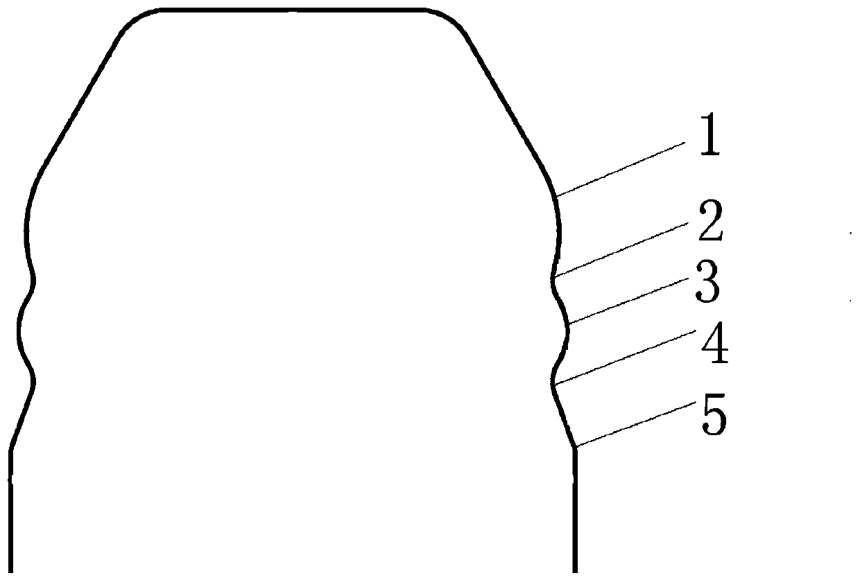
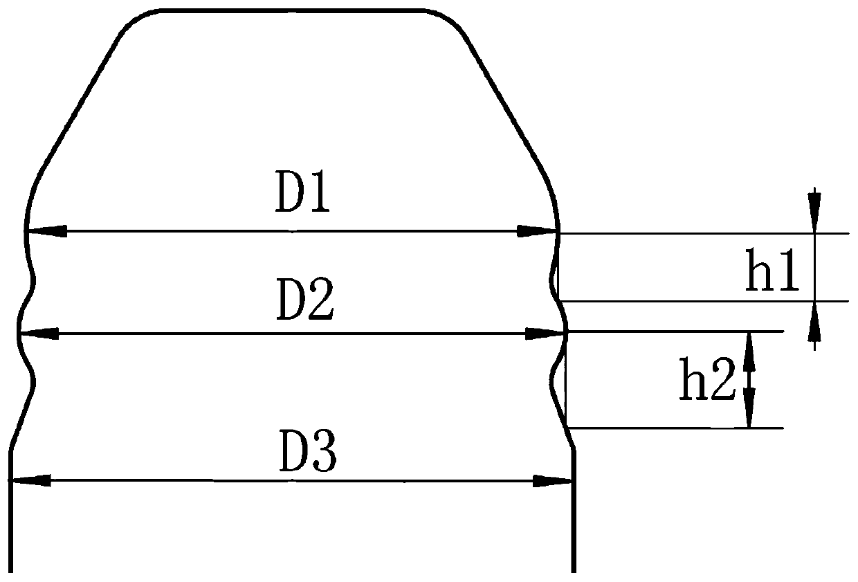
[0031] figure 1 It is a structural schematic diagram of the thinning and boring punch of the preferred embodiment of the present invention; figure 2 It is a schematic diagram of the structure size of the thinning and boring punch in the preferred embodiment of the present invention.

[0032] Such as figure 1As shown, the thinning and reaming punch of this embodiment includes a first punch section 1 located at the starting end of the punch, a second punch section 3 located downstream of the first punch section 1, and a second punch section 3 located downstream of the first punch section. The first transition section 2 between section 1 and the second punch section 3, the third punch section 5 located downstream of the second punch section 3, and the third punch ...


PUM


Abstract

The invention discloses a thinned hole flanging punch, a punch design method and an anti-deformation structure. The thinned hole flanging punch comprises a first punch section located at the initial end of the punch, a second punch section arranged downstream the first punch section, a first transition section located between the first punch section and the second punch section, a third punch section arranged downstream the second punch section, and a second transition section located between the second punch section and the third punch section. The diameter of the initial end of the second punch section is smaller than or equal to that of the tail end of the first punch section. The diameter of the tail end of the second punch section is greater than that of the tail end of the first punch section. The diameter of the first punch section and the diameter of the initial end of the second punch section are both greater than that of the first transition section. The diameter of the initial end of the third punch section is smaller than or equal to that of the tail end of the second punch head. The diameter of the tail end of the third punch section is greater than that of the tail end of the second punch section. The diameter of the tail end of the second punch head and the diameter of the initial end of the third punch head are both greater than that of the second transition section.

Description

technical field [0001] The invention relates to the technical field of hole-turning forming, in particular to a thinning hole-turning punch and a design method thereof. Background technique [0002] Flipping is used to turn the edge of the hole into a vertical edge. Flipping is a stamping process that turns the material into a side flange along the inner hole. The punch, the metal part on the stamping die in the mechanical tool, is installed on the stamping die for continuous punching and punching operations, so that the processed material is separated or plastically deformed, so as to obtain the required finished or semi-finished products. [0003] The aero-engine casing needs to be processed with multiple turning holes for welding other parts. In the prior art, a conventional hole punching punch is used for punching. The wall thickness of the turning hole formed by stamping is the same as that of the casing, but Because the wall thickness of the parts to be welded is much...

Claims


Application Information

Patent Timeline
Patent Type & Authority Patents(China)
IPC IPC(8): B21D37/10
CPCB21D37/10
Inventor 易洲宇顾庆军向建华姜嫄嫄马鑫
Owner CHINA HANGFA SOUTH IND CO LTD
Why Eureka
Try Eureka