
Installation adjustment structure for electromechanical product internal power machinery

A technology for power machinery and electromechanical products, applied in the field of installation and adjustment structures, can solve problems such as inability to adapt to work needs, inconvenient adjustment of position, inconvenient installation and disassembly, etc., to achieve convenient and fast position adjustment, convenient and fast installation, and later maintenance and replacement. simple effect

Active Publication Date: 2019-01-04
何贞芳
View PDF6 Cites 1 Cited by
  • Summary
  • Abstract
  • Description
  • Claims
  • Application Information

AI Technical Summary

Problems solved by technology

[0003] However, the installation structure of existing power machinery still has certain deficiencies in use.
Existing power machinery is often directly installed inside the electromechanical equipment through bolts. It is inconvenient to adjust the position during the installation process. When the position needs to be changed, it needs to use a lot of force to push the power machinery to move, which is laborious and laborious, and the work efficiency is low. trouble
The installation type of power machinery or the installation of the same power machinery in different electromechanical equipment will have different installation positions, and the power machinery needs to be adjusted, which cannot adapt to different work needs.
Moreover, the electromechanical equipment has poor stability during use, is prone to shaking, and is inconvenient to install and disassemble.

Method used


Image

  • Installation adjustment structure for electromechanical product internal power machinery
  • Installation adjustment structure for electromechanical product internal power machinery
  • Installation adjustment structure for electromechanical product internal power machinery

Examples


Embodiment Construction

[0031] The technical solutions of the present invention will be clearly and completely described below in conjunction with the embodiments. Apparently, the described embodiments are only some of the embodiments of the present invention, not all of them. Based on the embodiments of the present invention, all other embodiments obtained by persons of ordinary skill in the art without creative efforts fall within the protection scope of the present invention.

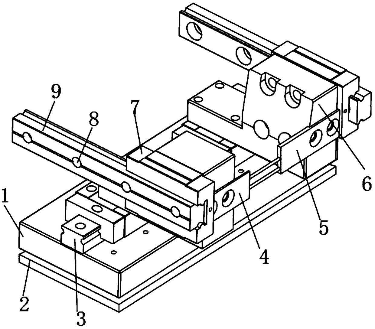
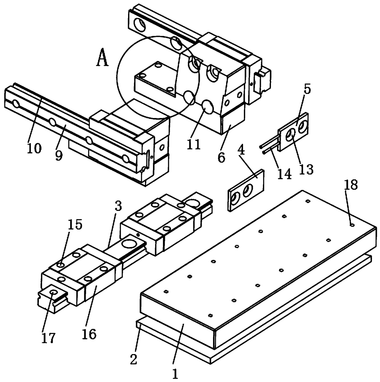
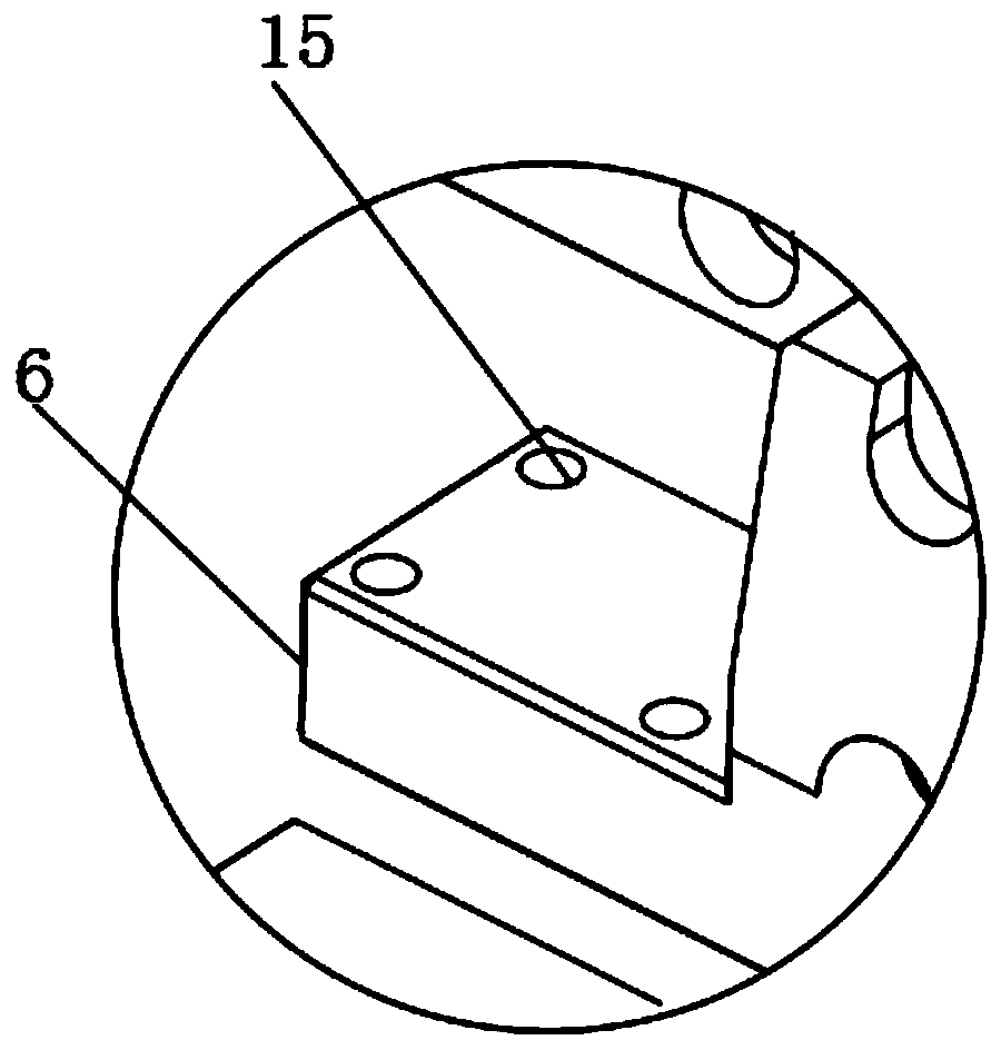
[0032] see Figure 1-7 As shown, an installation and adjustment structure for internal power machinery of electromechanical products, including a base 1, a fixed seat 2 and a limit seat 6, the bottom of the base 1 is horizontally connected to the fixed seat 2, and the top middle end of the fixed seat 2 is connected to the base 1 A rotating shaft 24 is installed between them, and several sleeves 25 are evenly installed around the rotating shaft 24 on the top of the fixed seat 2, and a support rod 28 is set inside the top of ...


PUM


Abstract

The invention discloses an installation adjustment structure for electromechanical product internal power machinery. The structure comprises a base, a fixed base and limiting bases; the bottom of thebase is horizontally connected with the fixed base; a rotating shaft is mounted between the middle end of the top of the fixed base and the base; a first slide rail is fixedly mounted at the middle end of the top of the base in the length direction; slide blocks are clamped at two ends of the top of the first slide rail; the limiting bases are mounted at the tops of the slide blocks; clamping blocks are welded on one sides of the limiting bases; second slide rails are clamped on the limiting bases through the clamping blocks; the projected ends of the two limiting bases are connected with a first side plate and a second side plate; and two sets of connecting rods are connected between the first side plate and the second side plate. The adjustment structure is convenient for installation and disassembly of power machinery in electromechanical equipment in use, can guarantee the working stability, is more convenient for use in the power machinery, and meets different working demands.

Description

technical field [0001] The invention relates to an adjustment structure, in particular to an installation adjustment structure for internal power machinery of electromechanical products. Background technique [0002] Machinery refers to the general term for machines and mechanisms. Machinery is a tool device that can help people reduce the difficulty of work or save labor. Items such as chopsticks, brooms, and tweezers can all be called machines, and they are simple machines. A complex machine is composed of two or more simple machines. These more complex machines are usually called machines. From the point of view of structure and motion, there is no difference between a mechanism and a machine, and it is generally called a machine. During the use of electromechanical equipment, it is often necessary to install different power machinery with installation structures to ensure the stable operation of electromechanical equipment. [0003] But the installation structure of ...

Claims


Application Information

Patent Timeline
Patent Type & Authority Applications(China)
IPC IPC(8): B23P19/10
Inventor 张晓曼
Owner 何贞芳
Learn More