Mechanism for adjusting moments of inertia

A technology of moment of inertia and adjustment mechanism, applied in the direction of rotation vibration suppression, testing of machine/structural components, measuring devices, etc., can solve the problem of single target, periodic or cyclical change of moment of inertia, and inability to conveniently simulate different moment of inertia or eccentricity Situation and other issues

Active Publication Date: 2019-01-04
ANHUI JIANGHUAI AUTOMOBILE GRP CORP LTD
View PDF10 Cites 0 Cited by
  • Summary
  • Abstract
  • Description
  • Claims
  • Application Information

AI Technical Summary

Problems solved by technology

Disadvantages of this solution: the characteristics of the rotating component itself are changed, it is not suitable for temporarily changing the moment of inertia, the moment of inertia cannot be changed during operation, and the moment of inertia cannot be changed periodically or cyclically
Disadvantages of this method: the rotating parts need to be reprocessed, the processing is difficult, time-consuming and labor-intensive, only a single goal can be achieved, and different moment of inertia or eccentricity can not be simulated conveniently and with multiple boundary conditions, the moment of inertia cannot be changed during operation, and the cycle cannot be Sexual or cyclical change of moment of inertia

Method used


Image

  • Mechanism for adjusting moments of inertia
  • Mechanism for adjusting moments of inertia
  • Mechanism for adjusting moments of inertia

Examples


Embodiment Construction

[0051] Embodiments of the present invention are described in detail below, examples of which are shown in the drawings, wherein the same or similar reference numerals designate the same or similar elements or elements having the same or similar functions throughout. The embodiments described below by referring to the figures are exemplary only for explaining the present invention and should not be construed as limiting the present invention.

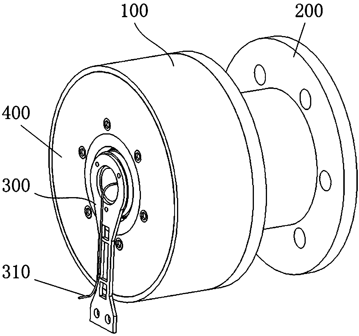
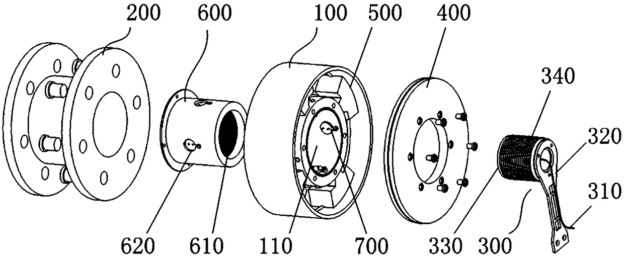
[0052] Please also refer to Figure 1 to Figure 4 , the embodiment of the present invention provides a moment of inertia adjustment mechanism, which includes a body 100, more than two sliders 500 with different quality specifications, a first conductive coil 610 trigger 700, a brush assembly 300, a control device and a connection Disk 200.

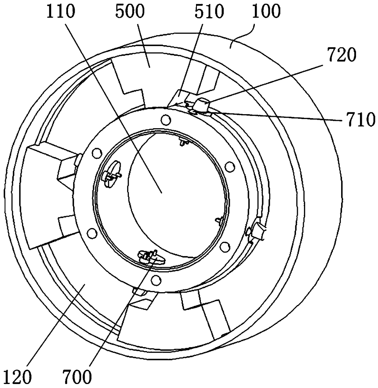
[0053]Wherein, the body 100 is provided with an installation cavity 120 , and the slider 500 is slidably disposed in the installation cavity 120 . When the number of sliders 500 is two, the quality...


PUM


Abstract

The invention discloses a mechanism for adjusting moments of inertia. The mechanism comprises a body, two or more sliders of different masses, a mounting seat, a trigger, a brush assembly, a control device and a connecting plate. The body is provided with a mounting cavity and a through hole, and the sliders are arranged in the mounting cavity. The mounting seat fixedly passes the through hole, and the first conductive coil is arranged in the mounting seat. A triggering end of the trigger is in contact with the sliders, and a conductive end of the trigger is connected to the first conductive coil. A second conductive coil connected to the first conductive coil is arranged in the brush assembly. The control device is connected to an output end of the second conductive coil. One end of the connecting plate is fixedly connected to the body, and the other end of the connecting plate is used for connecting a rotating member. According to the mechanism for adjusting moments of inertia provided by the invention, the simulated control of different moments of inertia and eccentric boundary conditions is achieved.

Description

technical field [0001] The invention relates to the technical field of moment of inertia control, in particular to a moment of inertia adjustment mechanism. Background technique [0002] In the current mechanical equipment, rotating parts can be seen everywhere. The functions realized during the rotating process are various, and the rotating speed is also different. There are high-speed rotating parts and low-speed rotating parts. The rotating mechanism will generate inertia when it rotates, and the inertia is generally measured by the moment of inertia, which is an important parameter in scientific experiments, engineering technology, aerospace, electric power, machinery, instrumentation and other industrial fields. [0003] For a rotating part, especially a high-speed rotating part, it is often necessary to know the magnitude of its moment of inertia first, and secondly to know the degree of influence of the change of moment of inertia on the performance and strength of th...

Claims


Application Information

Patent Timeline
Patent Type & Authority Applications(China)
IPC IPC(8): G01M1/10F16F15/20
CPCF16F15/20G01M1/10
Inventor 谢飞飞曹文霞李英涛宋长青张敬东郭强强张大晴周聪
Owner ANHUI JIANGHUAI AUTOMOBILE GRP CORP LTD
Why Eureka
Try Eureka