An infusion bottle hanger box for automatic bottle change

An infusion bottle and automatic technology, applied in the field of medical devices, can solve the problems of low efficiency, unexpected occurrence, and occupation of medical resources, and achieve the effect of saving medical resources and accelerating fluid drainage

Active Publication Date: 2021-03-05
济宁景泽信息科技有限公司
View PDF9 Cites 0 Cited by
  • Summary
  • Abstract
  • Description
  • Claims
  • Application Information

AI Technical Summary

Problems solved by technology

In the existing infusion process, when the medicine in the infusion bottle is about to be infused, the patient will usually notify the nurse station through the bedside button, and the nurse will carry the medicine to change the bottle. This traditional way of changing the bottle is not only inefficient , takes up a lot of medical resources, and after the nurse station receives the patient's call, it is generally in a hurry out of consideration for the patient's safety, and it is easy to take the medicine by mistake, resulting in accidents.

Method used


Image

  • An infusion bottle hanger box for automatic bottle change
  • An infusion bottle hanger box for automatic bottle change
  • An infusion bottle hanger box for automatic bottle change

Examples


Embodiment 1

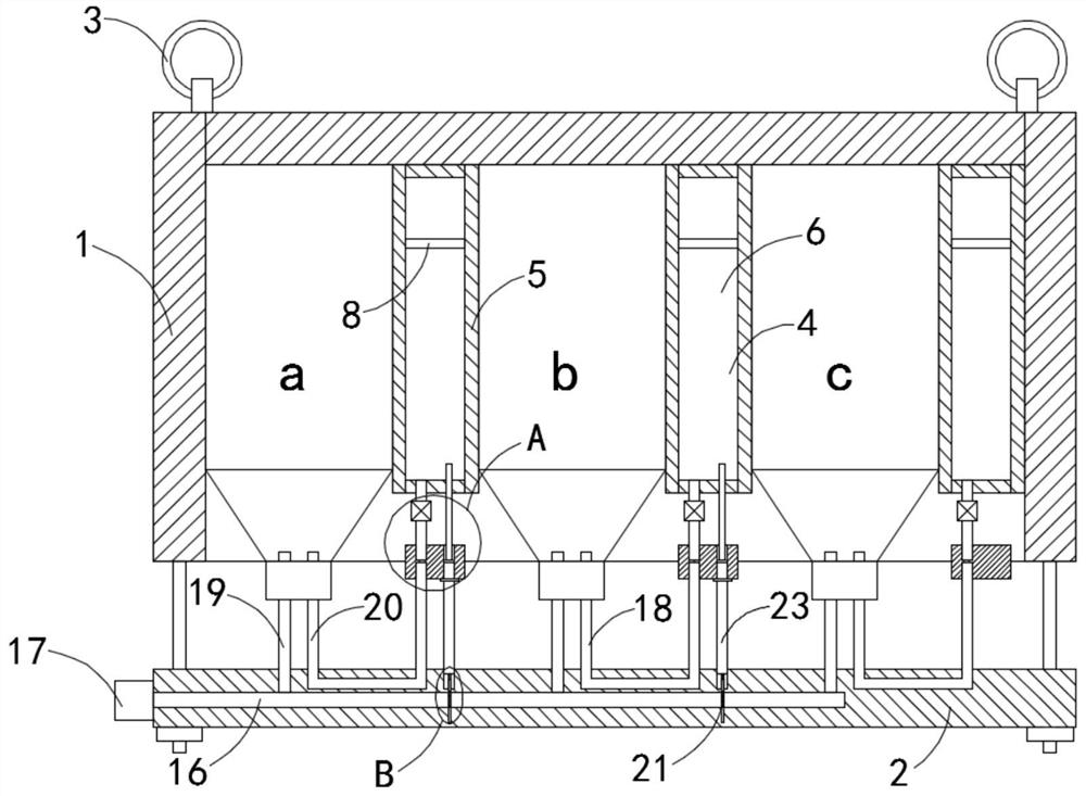
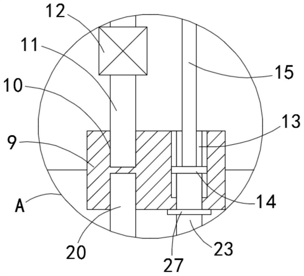
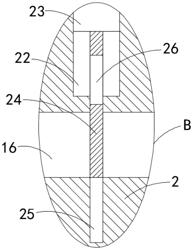
[0019] like Figure 1-4 As shown, an infusion bottle hanger box for automatic bottle change includes a box body 1 with an open lower end, a box cover 2 is provided below the box body 1, and the box cover 2 and box body 1 are detachably connected by bolts Specifically, the four corners of the box body 1 are fixedly connected with bolts, the box cover 2 is provided with through holes matching the bolts, the upper end of the box body 1 is fixedly connected with a plurality of suspension rings 3, and the box body 1 is provided with multiple A placement mechanism 4, the placement mechanism 4 includes a partition block 5, the upper end of the partition block 5 is fixedly connected with the inner top surface of the box body 1, the partition block 5 is provided with a cavity 6, and the top of the cavity 6 is provided with a connection with the outside The air inlet 7 and the sliding seal in the cavity 6 are connected with a movable plate 8, the gravity of the movable plate 8 is equal ...

Embodiment 2

[0025] like Figure 5 As shown, the difference between this embodiment and Embodiment 1 is that: the inner bottom surface of the cavity 6 is fixedly connected with a magnet sheet 28, the movable plate 8 is made of magnetic material, and the magnet sheet 28 and the movable plate 8 attract each other with opposite poles.

[0026] In this embodiment, when the infusion bottle is about to be transfused, the water pressure is low and the flow rate slows down. At this time, the movable plate 8 of magnetic material moves downwards close to the bottom of the cavity 6. Under the action of the magnet sheet 28, Attract the movable plate 8 downward to accelerate the liquid discharge.


PUM


Abstract

The invention belongs to the field of medical devices, in particular to an infusion bottle hanger box for automatic bottle change, which comprises a box body with an open lower end, a box cover is arranged below the box body, and bolts can be used between the box cover and the box body. Disassembly and connection, the upper end of the box body is fixedly connected with multiple suspension rings, and there are multiple placement mechanisms in the box body. The placement mechanism includes a partition block. , the upper part of the cavity is provided with an air inlet that communicates with the outside, a movable plate is connected with a sliding seal in the cavity, a connecting block is provided directly below the partition block, and corresponding slots are provided on the upper and lower side walls of the connecting block, located at An exhaust pipe is fixedly connected in the slot on the upper side, the upper end of the exhaust pipe communicates with the cavity, and a one-way valve is fixedly connected with the exhaust pipe. The present invention is provided with a cavity and a movable plate, and when the liquid medicine in the infusion bottle is infused, the movable plate is used to realize the effect of stopping the infusion and automatically changing the bottle, saving time and high efficiency, and saving medical resources.

Description

technical field [0001] The invention belongs to the field of medical devices, in particular to an infusion bottle hanger box for automatic bottle change. Background technique [0002] Family members or nurses are required to take care of the transfusion, and the bottle should be changed in time to prevent air from entering the blood and causing harm to the patient. In the existing infusion process, when the medicine in the infusion bottle is about to be infused, the patient will usually notify the nurse station through the bedside button, and the nurse will carry the medicine to change the bottle. This traditional way of changing the bottle is not only inefficient , Occupying a lot of medical resources, and after receiving a call from a patient, the nurse station is generally in a hurry out of consideration for the safety of the patient, and it is easy to take the medicine by mistake, resulting in accidents. [0003] For this reason, we propose a kind of transfusion bottle ...

Claims


Application Information

Patent Timeline
Patent Type & Authority Patents(China)
IPC IPC(8): A61M5/14A61M5/168
CPCA61M5/14A61M5/16822
Inventor 李捷尹永远
Owner 济宁景泽信息科技有限公司
Why Eureka
Try Eureka