A main truss adjustable safety channel
A safety channel and main truss technology, which is applied in the field of adjustable main truss safety channels, can solve the problems of occupying a large space, inconvenient installation and disassembly, and potential safety hazards, so as to improve work efficiency, increase stability, extend The effect of length
- Summary
- Abstract
- Description
- Claims
- Application Information
AI Technical Summary
Problems solved by technology
Method used
Image
Examples
Embodiment 1
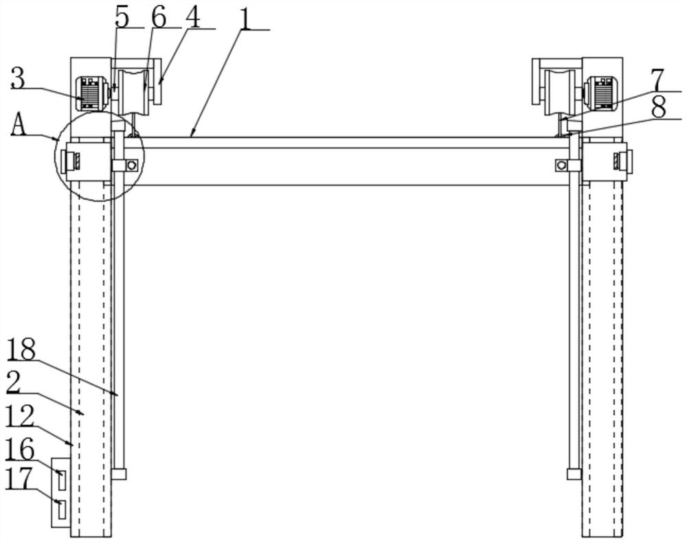
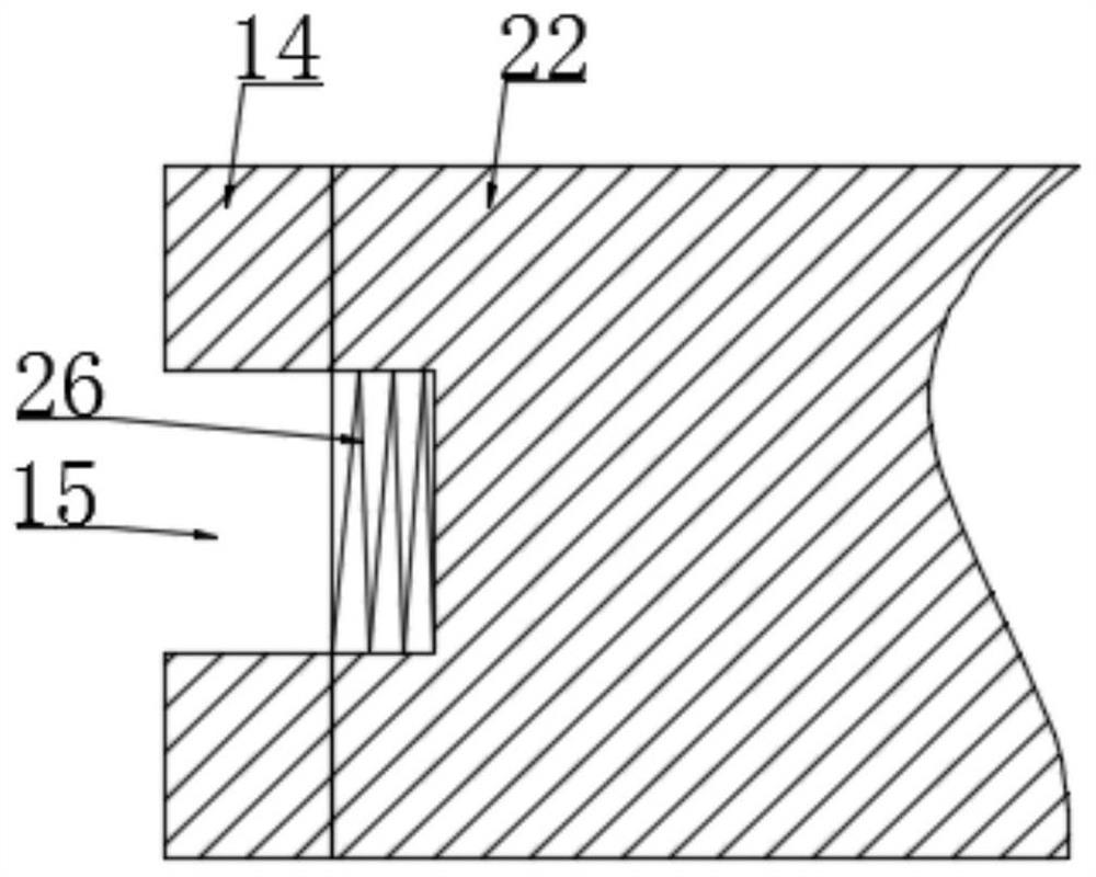
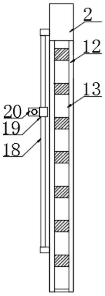
[0027] according to Figure 1-6 The main truss adjustable safety channel shown includes a main truss body 1, two support frames 2 symmetrically distributed on both sides of the main truss body 1, and a motor 3 is provided on the top of the support frame 2. A support plate 4 is provided on one side of the top of the support frame 2, a rotating shaft 5 is arranged between the support plate 4 and the support frame 2, a storage wheel 6 is provided on the outside of the rotating shaft 5, and a steel cable 7 is provided on the outside of the storage wheel 6 , the tops of both ends of the main truss body 1 are provided with hanging rings 8, the bottom ends of the steel cables 7 are fixedly connected with the hanging rings 8, and the outer side of the support frame 2 is sleeved with a connecting sleeve 9, and the connecting sleeve 9 is connected with the connecting sleeve 9. The main truss body 1 is fixedly connected, the side of the connecting sleeve 9 away from the main truss body 1...
Embodiment 2
[0030] according to Figure 1-3 In the main truss adjustable safety channel shown, a sliding rod 18 is provided on one side of the support frame 2, and a sliding sleeve 19 is slidably connected to the outer side of the sliding rod 18, and a fixed block is fixedly connected to one side of the sliding sleeve 19 20. The surface of the fixed block 20 is provided with a threaded hole, and the threaded hole is provided with a connecting screw 21, and the connecting screw 21 is threaded with the main truss body 1, and the sliding rod 18, the sliding sleeve 19 and the connecting screw are provided 21. Place the main truss body 1 between the two support frames 2, and make the slider 14 slide in the slide rail 12. A slide bar 18 is provided on one side of the support frame 2, and a sliding sleeve 19 is slidably connected to the outside of the slide bar 18. Use the connecting screw 21 to fix the fixed block 20 with the main truss body 1, so that the two sides of the main truss body 1 can...
PUM
 Abstract
Description
Claims
Application Information
 - R&D
- Intellectual Property
- Life Sciences
- Materials
- Tech Scout
- Unparalleled Data Quality
- Higher Quality Content
- 60% Fewer Hallucinations
Browse by: Latest US Patents, China's latest patents, Technical Efficacy Thesaurus, Application Domain, Technology Topic, Popular Technical Reports.
© 2025 PatSnap. All rights reserved.Legal|Privacy policy|Modern Slavery Act Transparency Statement|Sitemap|About US| Contact US: help@patsnap.com


