Control method and device, and switch

A control method and control device technology, applied in the electronic field, can solve problems such as user inconvenience, waste of power resources, and users forgetting to turn off

Active Publication Date: 2019-01-11
BEIJING SOGOU TECHNOLOGY DEVELOPMENT CO LTD
View PDF8 Cites 0 Cited by
  • Summary
  • Abstract
  • Description
  • Claims
  • Application Information

AI Technical Summary

Problems solved by technology

[0003] In practical applications, since one smart switch can control multiple different electrical equipment, and there are usually many electrical equipment in the home, it may happen that the user forgets to turn off some electrical equipment, resulting in a waste of power resources
Moreover, the user needs to check whether the electrical equipment in the home is turned off one by one, which brings inconvenience to the user.

Method used


Image

  • Control method and device, and switch
  • Control method and device, and switch
  • Control method and device, and switch

Examples


example 1

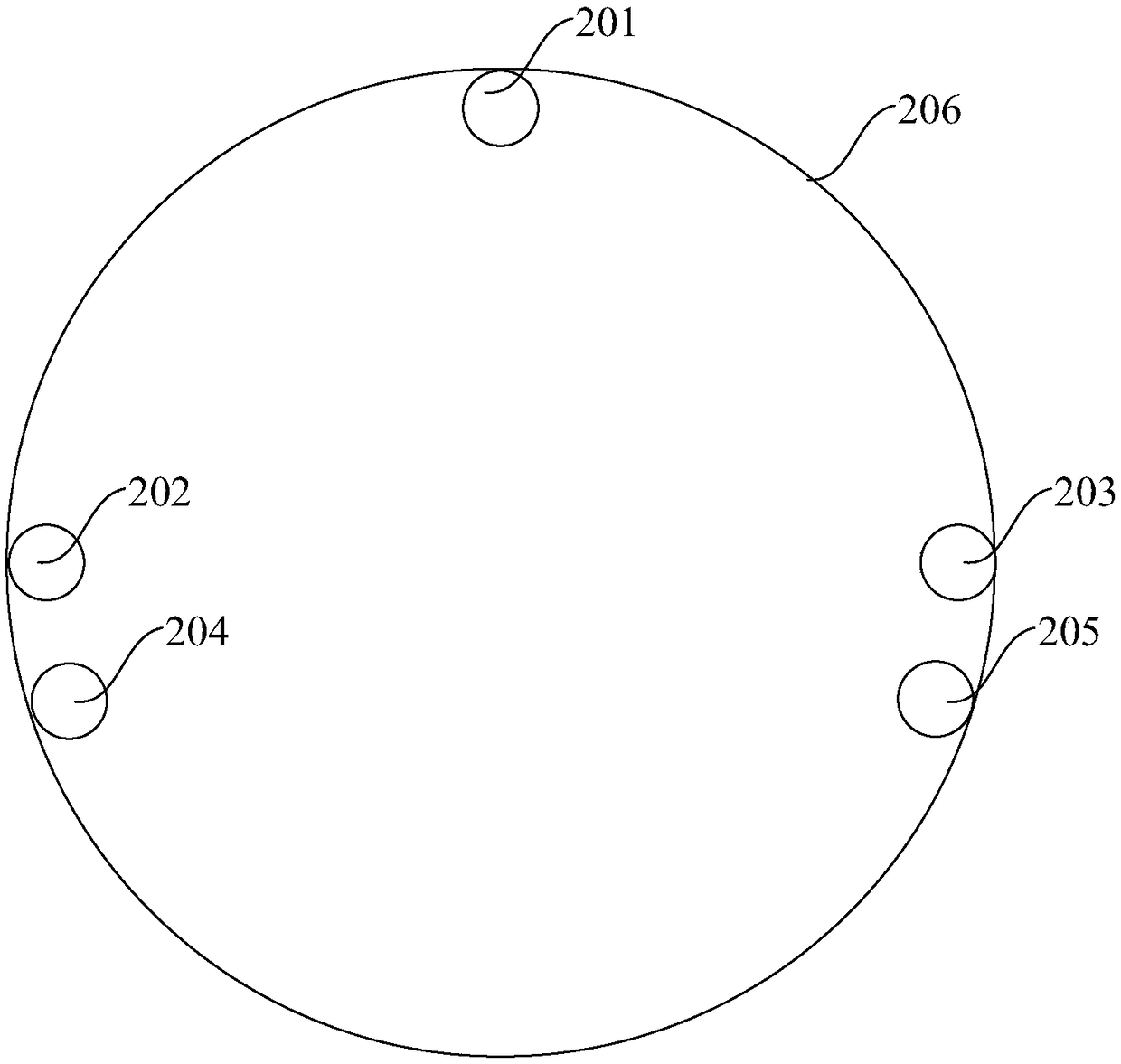
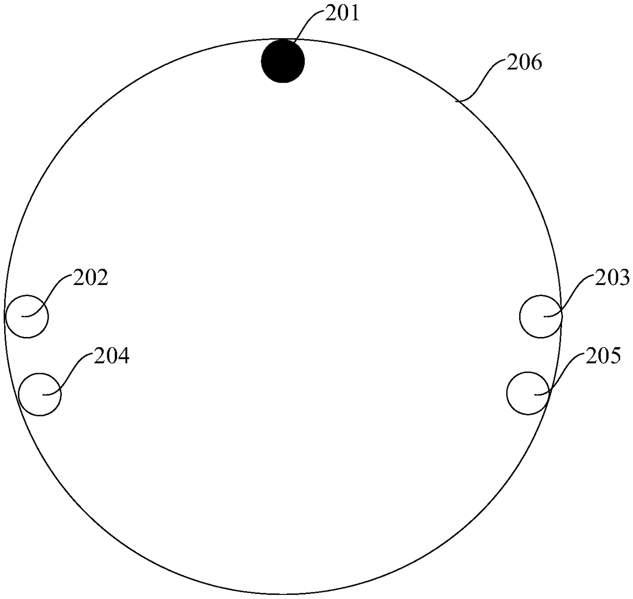
[0070] by figure 2 Take the circular light guide plate shown as an example, assuming that the maximum number of circuits that can be connected to the switch is 3, and the number of circuits currently connected to the switch is 1, then firstly, according to the number of circuits connected to 1, determine The number of target light-emitting elements is 1, because only one target light-emitting element can be selected in the case of only one access circuit, and since one target light-emitting element is less interfered by other light-emitting elements, any When a light emitting element is used as a target light emitting element, it can be considered that the target light emitting element satisfies the principle of uniform distribution. Therefore, one of the plurality of light-emitting elements can be randomly selected as the target light-emitting element; or a certain light-emitting element can be preset as the target light-emitting element when the number of connected circuits...

example 2

[0072] by figure 2 The circular light guide plate shown is taken as an example, assuming that the maximum number of circuits that can be connected to the switch is 3, and the number of circuits currently connected to the switch is 2, then firstly, according to the number of circuits connected to 2, determine The number of target light-emitting elements is 2; then, in figure 2 Among the 5 light-emitting elements, select 2 light-emitting elements evenly distributed inside the display panel as target light-emitting elements, for example, light-emitting element 202 and light-emitting element 203 may be selected as target light-emitting elements.

example 3

[0074] by figure 2 Take the circular light guide plate shown as an example, assuming that the maximum number of circuits that can be connected to the switch is 3, and the number of circuits currently connected to the switch is 3, then firstly, according to the number 3 of the connected circuits, determine The number of target light-emitting elements can be 3; then, in figure 2 Among the 5 light-emitting elements, select 3 light-emitting elements that are evenly distributed inside the display panel as the target light-emitting elements, for example, light-emitting element 201, light-emitting element 204, and light-emitting element 205 are uniformly distributed on the display panel at 120° Inside, therefore, the light emitting element 201, the light emitting element 204, and the light emitting element 205 can be selected as target light emitting elements.

[0075] In practical applications, when the number of access circuits is greater than 3, the implementation process is si...


PUM


Abstract

The embodiment of the invention provides a control method and device, and a device for control. The control method is applied to a switch; and a plurality of light emitting elements is arranged insidea display panel of the switch. The control method specifically comprises the following steps: determining the number of connected circuits and the conducting states of the connected circuits; and controlling the plurality of light emitting elements according to the number of the connected circuits and the conducting states of the connected circuits, so that the display states of the plurality oflight emitting elements are matched with the number and the conducting states. The embodiment of the invention can provide information of user equipment to the user through the display states, therebyimproving the convenience of the user using the switch.

Description

technical field [0001] The invention relates to the field of electronic technology, in particular to a control method, device and switch. Background technique [0002] With the development of electronic technology, smart switches have gradually replaced the old mechanical switches. Centralized control of multiple external devices (such as electrical equipment) can be realized through a smart switch. convenient. [0003] In practical applications, since one smart switch can control multiple different electrical equipment, and there are usually many electrical equipment in the home, it may happen that the user forgets to turn off some electrical equipment, resulting in a waste of power resources. And, the user needs to check whether the electrical equipment in the home is closed one by one, which brings inconvenience to the user. Contents of the invention [0004] Embodiments of the present invention provide a control method, a device, and a control device, which can prov...

Claims


Application Information

Patent Timeline
Patent Type & Authority Applications(China)
IPC IPC(8): G05B15/02
CPCG05B15/02
Inventor 王颖王硕赖国富张延超
Owner BEIJING SOGOU TECHNOLOGY DEVELOPMENT CO LTD
Why Eureka
Try Eureka