Eureka AIR delivers breakthrough ideas for toughest innovation challenges, trusted by R&D personnel around the world.

A catenary wire state detection device and detection method

A state detection device and detection method technology, applied in the direction of measuring devices, optical devices, instruments, etc., can solve the problems of not fully reflecting the real situation of the equipment, being easily affected by environmental factors, and being affected by the normal operation of railways, so as to facilitate popularization and use. , low cost and simple structure

Active Publication Date: 2018-03-20
JINAN UNIVERSITY
View PDF6 Cites 0 Cited by
  • Summary
  • Abstract
  • Description
  • Claims
  • Application Information

AI Technical Summary

Problems solved by technology

However, because the catenary is completely exposed to the outdoors and is easily affected by environmental factors, its wires will bend after a period of time. At this time, it is necessary to find the location of the bend in time and adjust it
[0003] At present, China's electrified railway is developing rapidly, but the maintenance of traction power supply equipment still adopts the method of regular power outage inspection and maintenance test. The test results obtained by this test method cannot fully reflect the real situation of the equipment in the actual operating state, and the power failure will affect the normal operation of the railway. have a certain impact

Method used


Image

  • A catenary wire state detection device and detection method
  • A catenary wire state detection device and detection method
  • A catenary wire state detection device and detection method

Examples


Embodiment 1

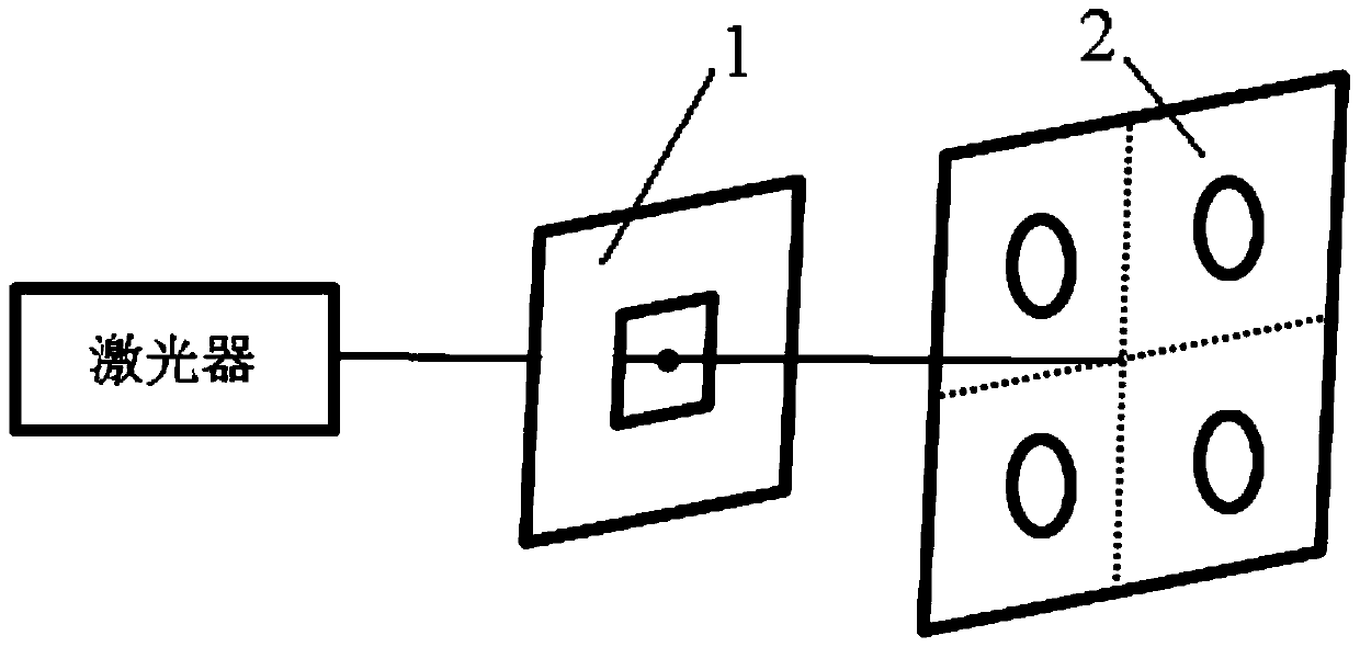
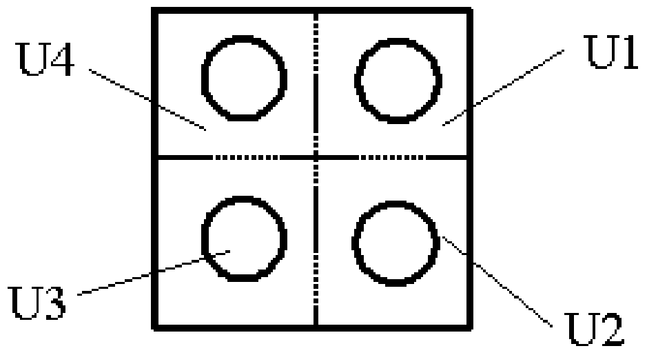
[0038] The catenary conductor state detection device of this embodiment includes a detection module and a signal processing device, and the detection module is as figure 1 As shown, it includes: a laser, a fixed plate 1 with a diverging device in the middle, a four-quadrant photovoltaic panel 2, and a wireless transmission module not shown in the figure. In actual use, a state detection device proposed by the present invention can be installed in key areas, so that each detection module corresponds to a signal processing device. It is also possible to set a state detection device proposed by the present invention on each section of catenary wire respectively, and all detection modules correspond to a signal processing device. At this time, a numbering is set on the wireless transmission module on each detection module, so that it can be convenient for the following Determine where the fault occurred based on the number. The above-mentioned laser is fixed on the bracket at one...


PUM


Abstract

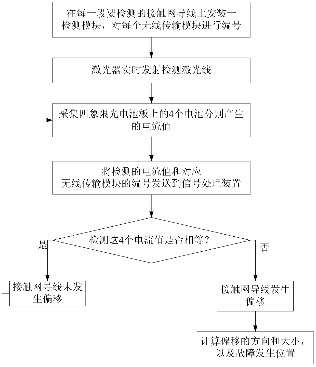
The invention discloses a state detection apparatus and detection method for a lead of overhead contact line equipment. The apparatus comprises a plurality of detection modules and a signal processing device. The detection modules comprise lasers, fixation plates with divergent devices arranged in the middle, four-quadrant light cell panels and wireless transmission modules. The laser are fixed on a support at one end of the overhead contact line equipment, the fixation plates are fixed on the lead of the overhead contact line equipment, the four-quadrant light cell panels are installed on a support at the other end of the overhead contact line equipment, and the wireless transmission modules are connected with the signal processing device. When the lead of the overhead contact line equipment is not deviated, the centers of the emission light of the lasers, the centers of the divergent devices and the centers of the four-quadrant light cell panels are disposed at the same straight line. According to the method, whether the lead is deviated, a deviation direction and a deviation size can be calculated in accordance with the size of acquired voltage signals generated by each cell and the position relations among the lasers, the divergent devices and the four-quadrant light cell panels. The method has the advantages of simplicity, reliability, good real-time performance, low cost, convenient installation and easy maintenance.

Description

technical field [0001] The invention relates to the field of railway traction power supply, in particular to a catenary wire state detection device and detection method. Background technique [0002] The catenary wire is also called the tram line, which is an important part of the catenary. When the electric locomotive is in operation, the pantograph sliding plate directly contacts and rubs against the catenary wire, and obtains electric energy from the wire. Its performance and the selection of the cross-sectional area of ​​the contact wire should meet the requirements of traction power supply calculation. In order for the pantograph to obtain electric energy safely, it is required that the catenary wire should be kept as straight as possible without bending. However, because the catenary is completely exposed to the outdoors and is easily affected by environmental factors, its wires will bend after a period of time. At this time, it is necessary to find the location of th...

Claims


Application Information

Patent Timeline
Patent Type & Authority Patents(China)
IPC IPC(8): G01B11/00
Inventor 黄元亮钟佳琪刘袁龙杨潇周欣汶
Owner JINAN UNIVERSITY
Why Eureka
Eureka Blog
Learn More