Eureka AIR delivers breakthrough ideas for toughest innovation challenges, trusted by R&D personnel around the world.

Motor bearing mounting structure

A technology for mounting structures and motor bearings, which is applied in the direction of electromechanical devices, casings/covers/supports, electrical components, etc., can solve the problems of weak axial positioning ability of bearings, achieve low cost, improve sealing effect, and prevent grease from overflowing Effect

Inactive Publication Date: 2019-01-11
CRRC YONGJI ELECTRIC CO LTD
View PDF8 Cites 2 Cited by
  • Summary
  • Abstract
  • Description
  • Claims
  • Application Information

AI Technical Summary

Problems solved by technology

[0003] The invention solves the problem that the bearing axial positioning ability of the existing motor bearing installation structure is weak, and provides a motor bearing installation structure, which improves the axial positioning ability of the bearing and improves the sealing effect of the bearing at the same time

Method used


Image

  • Motor bearing mounting structure

Examples


Embodiment Construction

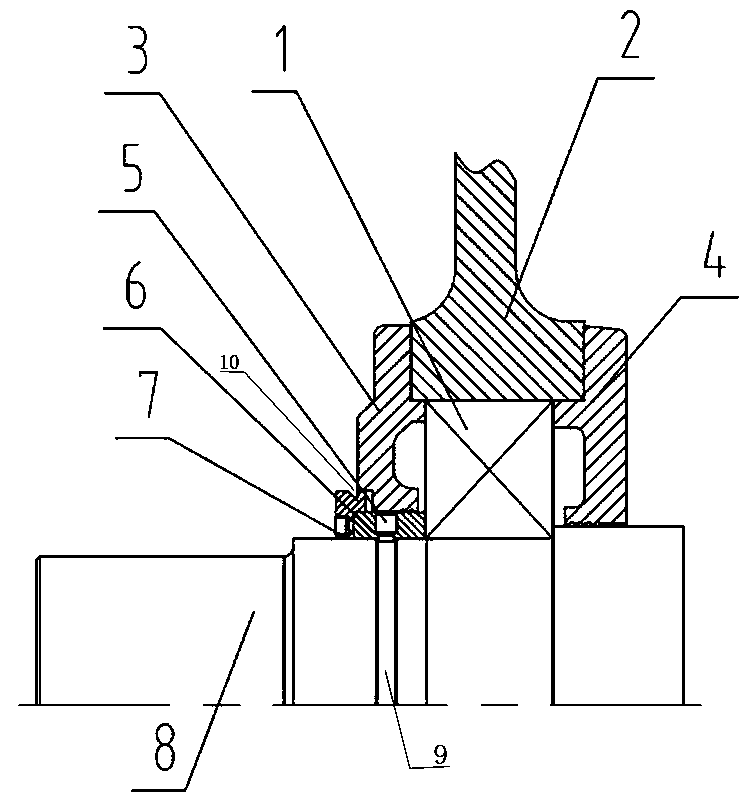
[0008] The motor bearing installation structure includes a shaft 8, a bearing 1, an end cover 2, an inner bearing cover 4, and an outer bearing cover 3. The oil stopper 6 is shrunk on the shaft 8, and the inner ring of the bearing 2 is formed by the shaft shoulder and the oil on the shaft 8. Block 6 is positioned, and oil block 6 outer ring surface and outer bearing cap 3 inner ring surfaces seal fit. There are (multiple) threaded holes evenly distributed around the oil retainer 6, and an annular radial groove 9 matching the position of the threaded holes is opened on the rotating shaft 8. The positioning pin 5 is screwed into the threaded hole so that the lower end of the positioning pin 5 extends into the radial direction. Groove 9, upper end are flush with the surface of oil retainer 6 outer rings or sink into the surface of oil retainer 6 outer rings. During specific implementation, a labyrinth sealing structure or an oil sealing groove sealing structure is provided betwee...


PUM


Abstract

The invention relates to a motor bearing mounting structure. The problem that the bearing axial positioning ability of the existing motor bearing mounting structure is weak is solved. The motor bearing mounting structure comprises a rotating shaft, a bearing, an end cover, an inner bearing cover and an outer bearing cover, wherein an oil stop is heat-sleeved on the rotating shaft, an inner ring ofthe bearing is positioned by a shaft shoulder and an oil stop on the rotating shaft, and an outer ring surface of the oil stop is sealingly matched with an inner ring surface of the outer bearing cover. A threaded hole is uniformly distributed around the oil stop, an annular radial groove matched with the position of the threaded hole is arranged on the rotating shaft, the positioning pin is screwed into the threaded hole so that the lower end of the positioning pin extends into the radial groove, and the upper end is flush with the surface of the oil stop outer ring or sunk into the surfaceof the oil stop outer ring. As that oil stop and the position pin are added, the axial position ability of the bearing is improved, axial movement of the bearing is reliably prevent, the sealing effect of the bearing is improved, and the grease overflow, the external dust, water and the like are effectively prevented from intruding into the interior of the bearing. The invention has the advantagesof convenient installation, simple whole structure process, low cost and obvious economic benefit.

Description

technical field [0001] The invention is a motor bearing installation structure. Background technique [0002] The motor bearing installation structure is the key to the long-term operation of the motor. The bearing installation structure of the motor usually consists of a bearing, an end cover, an inner bearing cover, and an outer. Bearings have a variety of bearing structures such as double-ball bearing structure, three-bearing structure, and double-bearing structure using ball and column joints. The assembly structure of the bearing caps at both ends is the same. The bearing is installed in the bearing cavity of the motor end cap. The bearing radial force point is basically in the middle of the bearing. The outer ring of the bearing is positioned by the bearing caps at both ends, and the bearing cap is connected to the end cap by bolts. . The inner oil chamber of the bearing cover provides oil storage, which is the main space filled with grease, and is generally filled ...

Claims


Application Information

Patent Timeline
Patent Type & Authority Applications(China)
IPC IPC(8): H02K5/10H02K5/16
CPCH02K5/10H02K5/163
Inventor 贾健符致昭靳宏杰李雪珍杨明浩张伟王春喜刘馨园
Owner CRRC YONGJI ELECTRIC CO LTD
Why Eureka
Eureka Blog
Learn More