A head fixing device for child examination

A fixation device and head technology, which is applied in the field of head fixation devices for children's examination, can solve the problems of children's head fixation and increased hospital manpower demand

Inactive Publication Date: 2019-01-15
孟庆和
View PDF5 Cites 7 Cited by
  • Summary
  • Abstract
  • Description
  • Claims
  • Application Information

AI Technical Summary

Problems solved by technology

[0003] In order to overcome the shortcomings that the medical staff cannot fix the child's head well, sending the medical staff to hold the child's head will also increase the manpower demand of the hospital. Therefore, the technical problem of the present invention is: to provide a A head immobilization device for children's examinations that immobilizes children's heads and reduces the manpower requirements for medical staff

Method used


Image

  • A head fixing device for child examination
  • A head fixing device for child examination

Examples


Embodiment 1

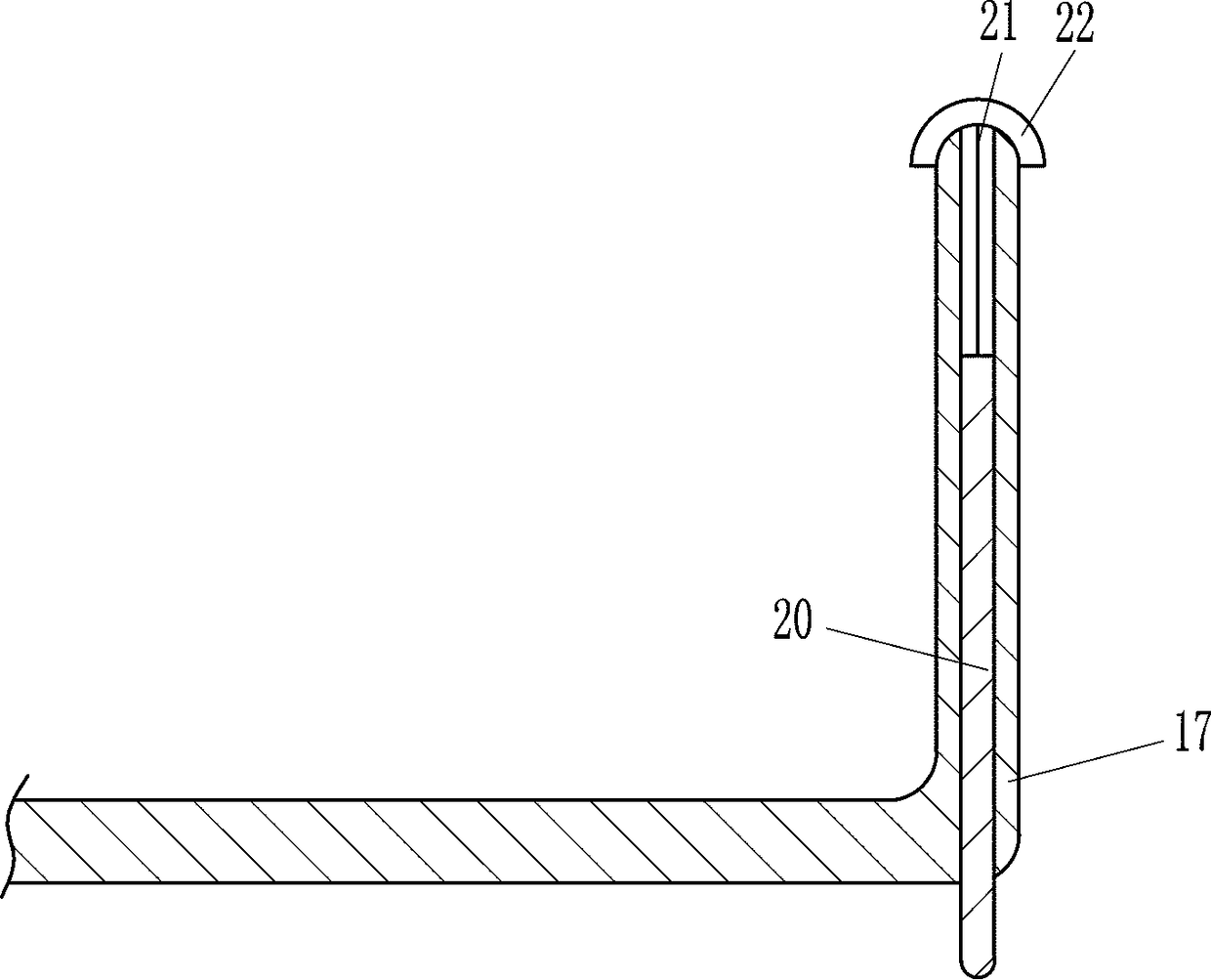
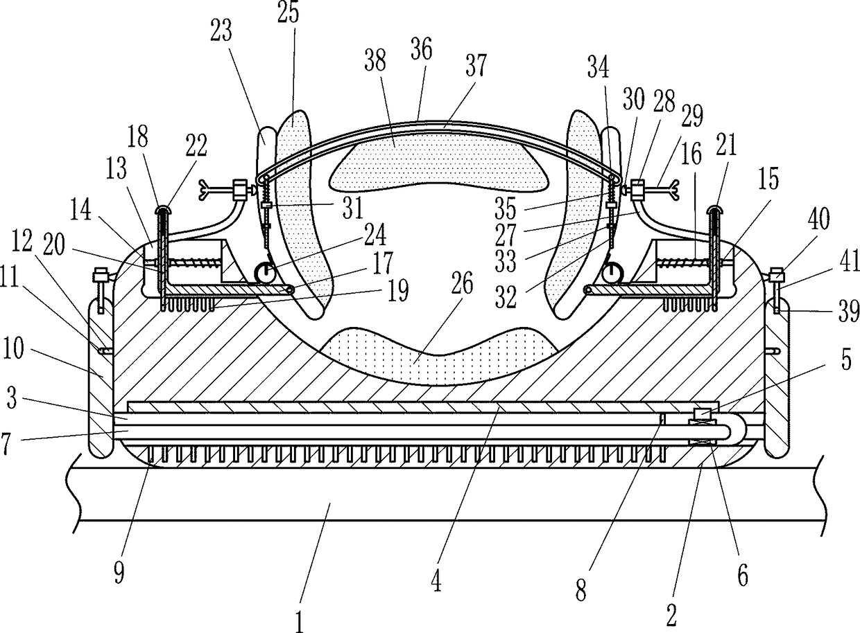
[0018] A head immobilization device for child examination, such as Figure 1-2 As shown, it includes arc plate 2, slide rail 4, slider 5, bearing seat 6, rotating shaft 7, clamp rod 8, clamp plate 10, insert block 12, guide rail 14, guide block 15, compression spring 16, L-shaped Rod 17, inserting rod 20, backguy 21, pull bar 22, connecting plate 23, torsion spring 24, the first sponge 25 and the second sponge 26, arc plate 2 is placed on the bed board 1, the front and back of the bottom of arc plate 2 The square is provided with an installation groove 3, and the top of the installation groove 3 is embedded with a slide rail 4, and a slider 5 is slid on the slide rail 4. The bottom of the slider 5 is connected with a bearing seat 6, and a rotating shaft is installed on the bearing seat 6. 7. The top right side of the front rotating shaft 7 and the top left side of the rear rotating shaft 7 are provided with clamping rods 8, and the curved plate 2 below the installation groove ...

Embodiment 2

[0020] A head immobilization device for child examination, such as Figure 1-2 As shown, it includes arc plate 2, slide rail 4, slider 5, bearing seat 6, rotating shaft 7, clamp rod 8, clamp plate 10, insert block 12, guide rail 14, guide block 15, compression spring 16, L-shaped Rod 17, inserting rod 20, backguy 21, pull bar 22, connecting plate 23, torsion spring 24, the first sponge 25 and the second sponge 26, arc plate 2 is placed on the bed board 1, the front and back of the bottom of arc plate 2 The square is provided with an installation groove 3, and the top of the installation groove 3 is embedded with a slide rail 4, and a slider 5 is slid on the slide rail 4. The bottom of the slider 5 is connected with a bearing seat 6, and a rotating shaft is installed on the bearing seat 6. 7. The top right side of the front rotating shaft 7 and the top left side of the rear rotating shaft 7 are provided with clamping rods 8, and the curved plate 2 below the installation groove ...

Embodiment 3

[0023] A head immobilization device for child examination, such as Figure 1-2 As shown, it includes arc plate 2, slide rail 4, slider 5, bearing seat 6, rotating shaft 7, clamp rod 8, clamp plate 10, insert block 12, guide rail 14, guide block 15, compression spring 16, L-shaped Rod 17, inserting rod 20, backguy 21, pull bar 22, connecting plate 23, torsion spring 24, the first sponge 25 and the second sponge 26, arc plate 2 is placed on the bed board 1, the front and back of the bottom of arc plate 2 The square is provided with an installation groove 3, and the top of the installation groove 3 is embedded with a slide rail 4, and a slider 5 is slid on the slide rail 4. The bottom of the slider 5 is connected with a bearing seat 6, and a rotating shaft is installed on the bearing seat 6. 7. The top right side of the front rotating shaft 7 and the top left side of the rear rotating shaft 7 are provided with clamping rods 8, and the curved plate 2 below the installation groove ...


PUM


Abstract

The invention relates to a head fixing device, in particular to a head fixing device for children examination. Therefore, the technical problem of the present invention is to provide a head fixing device for child examination which is capable of fixing a child's head well and reducing the demand for a medical worker. A technical scheme: the device comprises an arc plate, a slide rail, a slide block, a bearing seat, a rotating shaft, a clamping rod, a clamping plate, a plug block, a guide rail, a guide block, a compression spring, an L-shaped rod, a plug rod, a cable, etc.; the arc plate is arranged on the bed plate, the lower part of the arc plate is provided with mounting grooves on the front and back sides, a slide rail is embedded on the top of the mounting groove, and the slide block is arranged on the slide rail. The clamping rod and the clamping plate can be rotated by a rotating shaft when the clamping plate is rotated, so that the clamping rod can be inserted into the clampinggroove, and the clamping plate can be clamped on the left and right sides of the bed plate, so that the device can be fixed, and the device can be prevented from moving left and right during use.

Description

technical field [0001] The invention relates to a head fixing device, in particular to a head fixing device for children's inspection. Background technique [0002] When children carry out head examination, because children are active by nature and do not listen to instructions, children's heads are also easy to move around, which will affect the inspection of children's heads by medical staff. And at present lack the device that children's head can be fixed when checking children's head, generally hold down children's head by medical personnel when checking children's head, but some children are afraid of strangers, when medical personnel hold down their head May be afraid, and then start crying, which will further affect the process of checking the child's head. Sending medical staff to hold the child's head will also increase the manpower demand of the hospital, and it will not be able to fix the child's head well. Contents of the invention [0003] In order to overcom...

Claims


Application Information

Patent Timeline
Patent Type & Authority Applications(China)
IPC IPC(8): A61G13/12A61B90/00
CPCA61B90/08A61G13/121A61G13/126A61G2200/14A61G2203/70
Inventor 张日鑫
Owner 孟庆和
Why Eureka
Try Eureka