
Clamping mechanism and overturning structure employing same

A technology of clamping mechanism and inversion structure, which is applied in manufacturing tools, metal processing equipment, feeding devices, etc., can solve the problems of low efficiency of reclaiming and feeding, and achieve the effect of solving the problem of low efficiency of reclaiming and feeding.

Pending Publication Date: 2019-01-15
ZHUHAI GREE INTELLIGENT EQUIP CO LTD +1
View PDF0 Cites 0 Cited by
  • Summary
  • Abstract
  • Description
  • Claims
  • Application Information

AI Technical Summary

Problems solved by technology

[0004] The main purpose of the present invention is to provide a clamping mechanism and its overturning structure to solve the problem of low feeding and feeding efficiency of the clamping mechanism in the prior art

Method used


Image

  • Clamping mechanism and overturning structure employing same
  • Clamping mechanism and overturning structure employing same
  • Clamping mechanism and overturning structure employing same

Examples


Embodiment Construction

[0025] It should be noted that, in the case of no conflict, the embodiments in the present application and the features in the embodiments can be combined with each other. The present invention will be described in detail below with reference to the accompanying drawings and examples.

[0026] It should be pointed out that the following detailed description is exemplary and intended to provide further explanation to the present application. Unless defined otherwise, all technical and scientific terms used herein have the same meaning as commonly understood by one of ordinary skill in the art to which this application belongs.

[0027] It should be noted that the terminology used here is only for describing specific implementations, and is not intended to limit the exemplary implementations according to the present application. As used herein, unless the context clearly dictates otherwise, the singular is intended to include the plural, and it should also be understood that wh...


PUM


Abstract

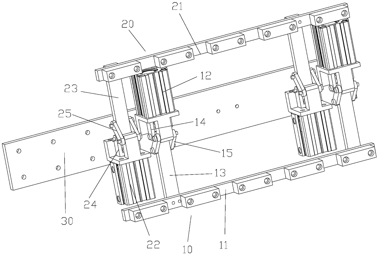
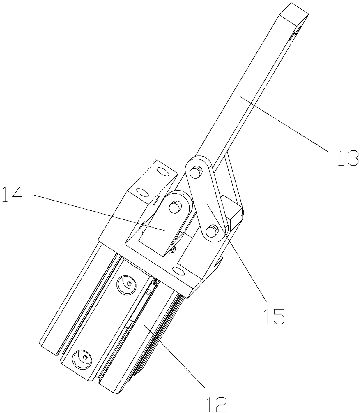
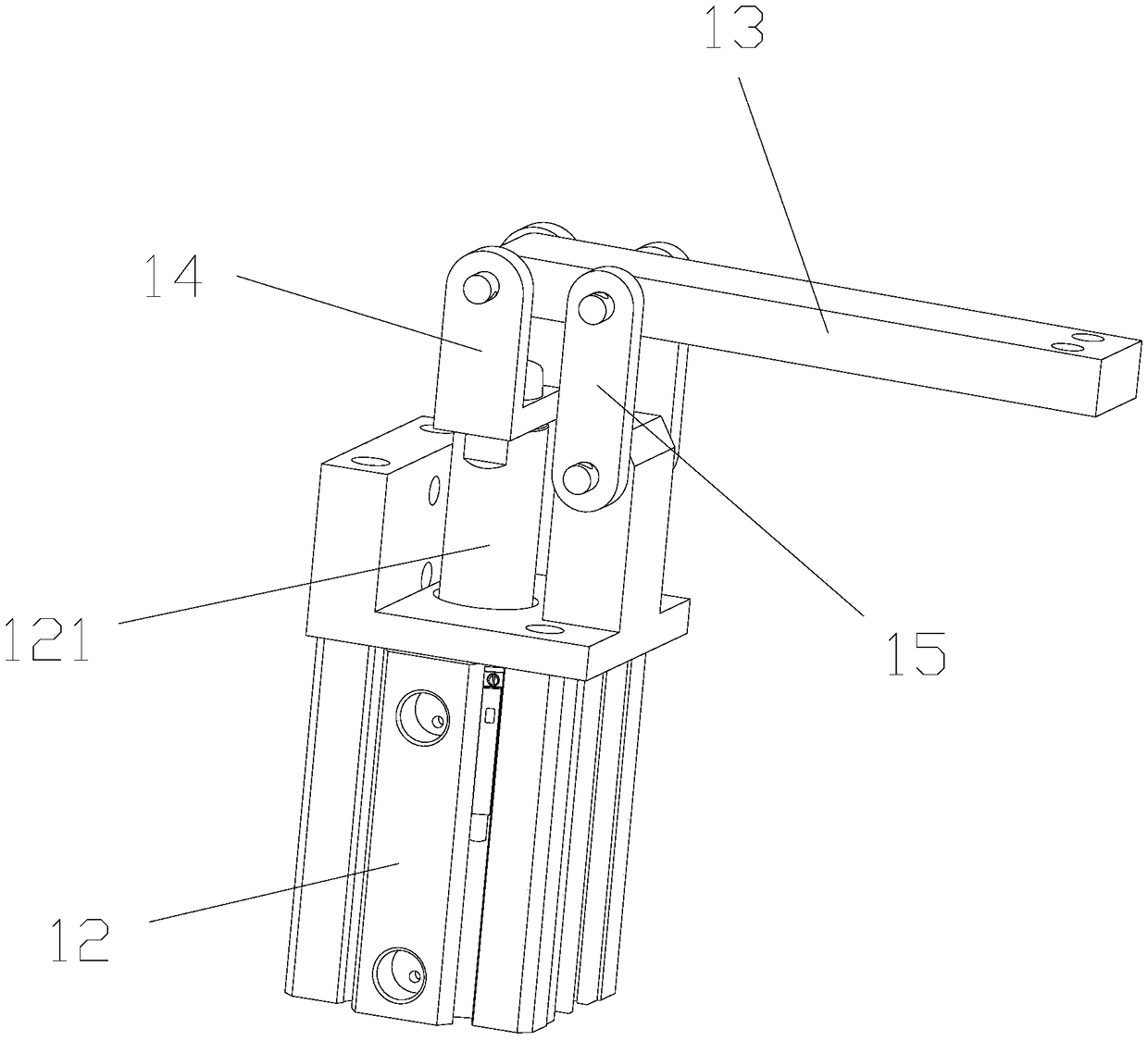
The invention provides a clamping mechanism and an overturning structure employing same. The clamping mechanism comprises a first clamping member comprising a first clamping portion; and a second clamping member including a second clamping portion, wherein the first clamping portion and the second clamping portion are used for clamping a preset component; at least one of the first clamping portionand the second clamping portion is rotatably disposed so as to allow the first clamping portion and the second clamping portion to tightly clamp or release the preset component. The clamping mechanism of the present invention solves the problem of low picking and feeding efficiency of a clamping mechanism in the prior art.

Description

technical field [0001] The invention relates to the field of material clamping machinery, in particular, to a clamping mechanism and its flipping structure. Background technique [0002] In the production process of sheet metal stamping connection, due to process requirements, sheet metal parts need to be turned over to achieve double-sided forming. In this process, the clamping mechanism is very important. It is not only necessary to ensure effective clamping of sheet metal parts, but also to Quickly clamp sheet metal parts to increase productivity. [0003] In the prior art, the clamping mechanism mostly adopts two relatively movable jaws to clamp the sheet metal part. When picking up the material, it is necessary to ensure that the whole moves along the direction close to the sheet metal part, and then clamp the workpiece. When unloading, the clamping mechanism needs to be moved as a whole after the jaws are opened. Since the entire feeding or feeding needs to move the c...

Claims


Application Information

Patent Timeline
Patent Type & Authority Applications(China)
IPC IPC(8): B21D43/04
CPCB21D43/04
Inventor 杨建新熊跃春柯振中薛乃凤邢旭辉
Owner ZHUHAI GREE INTELLIGENT EQUIP CO LTD
Learn More