Rail transit system and turnout beam thereof

A technology for rail transit and turnout beams, applied in the field of rail transit systems, which can solve problems such as the inability of the movable finger plate to fall back, poor flatness of the overlapping surface of the finger plate, and poor vehicle passing stability, so as to improve the vehicle passing stability , The effect of good vehicle passing stability and high reliability

Active Publication Date: 2019-01-15
BYD CO LTD
View PDF6 Cites 2 Cited by
  • Summary
  • Abstract
  • Description
  • Claims
  • Application Information

AI Technical Summary

Problems solved by technology

[0002] The turnout beam of the rail transit system in the related art realizes the docking through the finger plate structure, and the docking requirements are relatively high. If the offset occurs during the docking, the movable finger plate will not be able to fall back, and the connecting part of the movable connecting plate will be tilted, threatening the driving. Safety
A large distance is reserved between the end face of the

Method used


Image

  • Rail transit system and turnout beam thereof
  • Rail transit system and turnout beam thereof
  • Rail transit system and turnout beam thereof

Examples


Embodiment Construction

[0030] Embodiments of the present invention are described in detail below, examples of which are shown in the drawings, wherein the same or similar reference numerals designate the same or similar elements or elements having the same or similar functions throughout. The embodiments described below by referring to the figures are exemplary only for explaining the present invention and should not be construed as limiting the present invention.

[0031] The turnout girder 1 of a rail transit system according to an embodiment of the present invention will be described below with reference to the accompanying drawings.

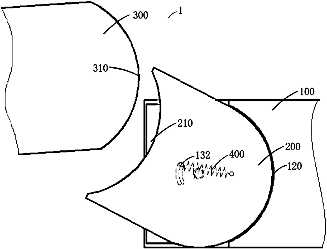
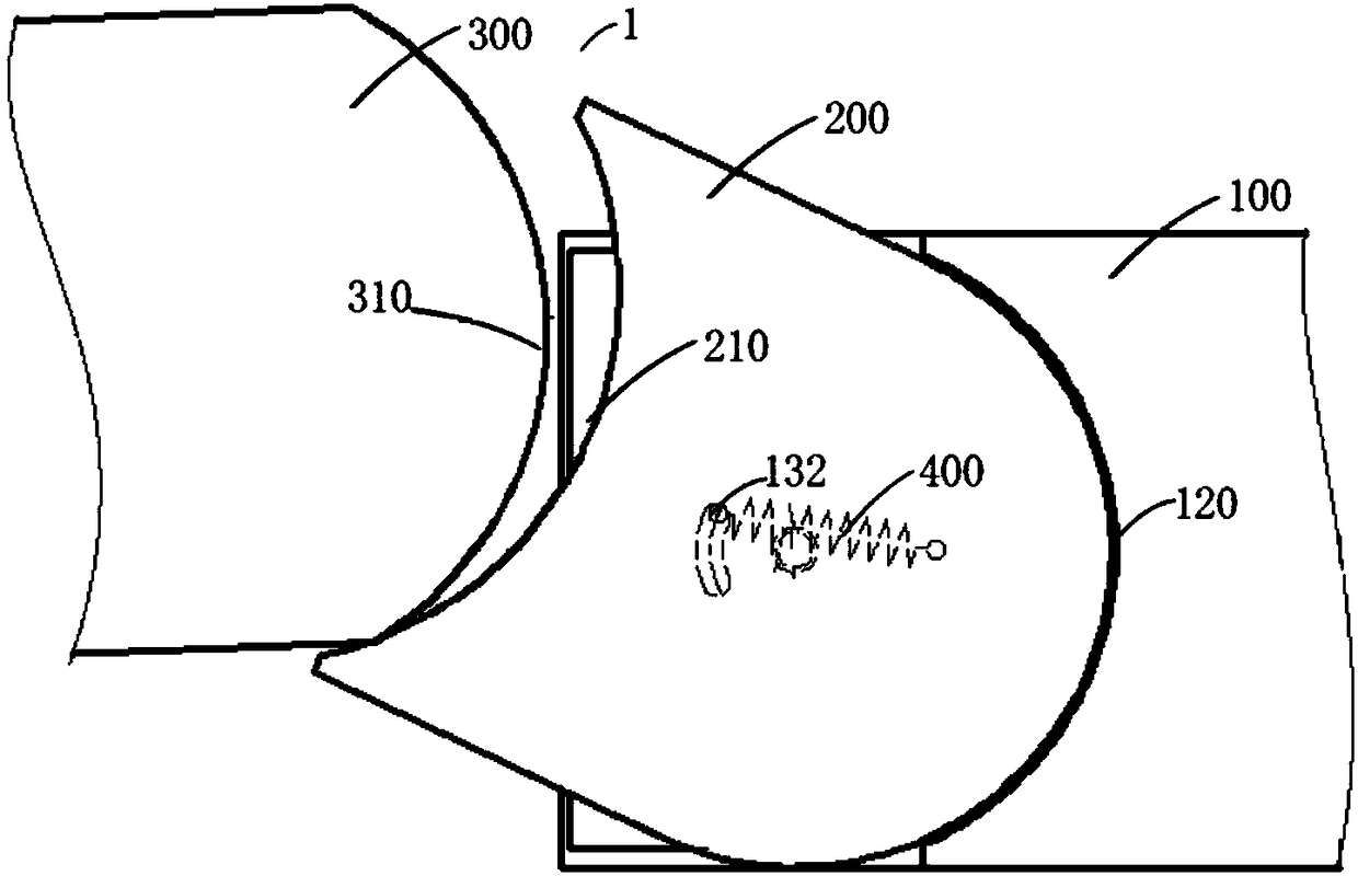
[0032] Such as Figure 1-Figure 6 As shown, the turnout beam 1 of the rail transit system according to the embodiment of the present invention includes a fixed beam 100 , a movable plate 200 and a movable beam 300 .

[0033] The fixed beam 100 is adapted to be fixedly connected with the track beam. The movable plate 200 is swingably arranged on the fixed beam 100...


PUM


Abstract

The invention discloses a rail transit system and a turnout beam thereof. The turnout beam of the rail transit system comprises a fixed beam which is adapted to be fixedly connected with the rail beam; a movable plate swingably arranged on the fixed beam, wherein a butt joint groove is arranged at one end of the movable plate away from the fixed beam; a movable beam provided with a butt joint surface on the end face of the movable beam facing the fixed beam, wherein one end of the movable beam adjacent to the fixed beam is adapted to fit in the butt joint groove. The turnout beam of the rail transit system according to the embodiment of the invention has the advantages of good vehicle passing stability, good safety and high reliability.

Description

technical field [0001] The invention relates to the technical field of rail transit systems, in particular to a turnout beam of a rail transit system and a rail transit system having the turnout beam of the rail transit system. Background technique [0002] The turnout beam of the rail transit system in the related art realizes the docking through the finger plate structure, and the docking requirements are relatively high. If the offset occurs during the docking, the movable finger plate will not be able to fall back, and the connecting part of the movable connecting plate will be tilted, threatening the driving. Safety. A large distance is reserved between the end face of the finger plate and the end face of the other side, so that there is a large gap on the end face after the butt joint is completed, and the flatness of the overlapping surface of the finger plate is not good, and the vehicle passing stability is poor. The direct collision of the finger plates makes the ...

Claims


Application Information

Patent Timeline
IPC IPC(8): E01B25/12
CPCE01B25/12
Inventor 邓义昭许理娄秋凤蔡仁财
Owner BYD CO LTD
Why Eureka
Try Eureka