Sliding door of anechoic chamber

A technology for sliding doors and anechoic chambers

Inactive Publication Date: 2019-01-15
SUZHOU ANKEN ELECTRONICS TECH
View PDF4 Cites 0 Cited by
  • Summary
  • Abstract
  • Description
  • Claims
  • Application Information

AI Technical Summary

Problems solved by technology

[0003] In addition, the existing sliding doors mainly realize the sliding function by setting a sliding mechanism under the door body. In order to ensure smooth sliding, there must be a gap under the sliding door, which will affect the sound insulation effect

Method used


Image

  • Sliding door of anechoic chamber
  • Sliding door of anechoic chamber
  • Sliding door of anechoic chamber

Examples


Embodiment Construction

[0022] The technical solution of the present invention will be described in further non-limiting detail below in combination with preferred embodiments and accompanying drawings.

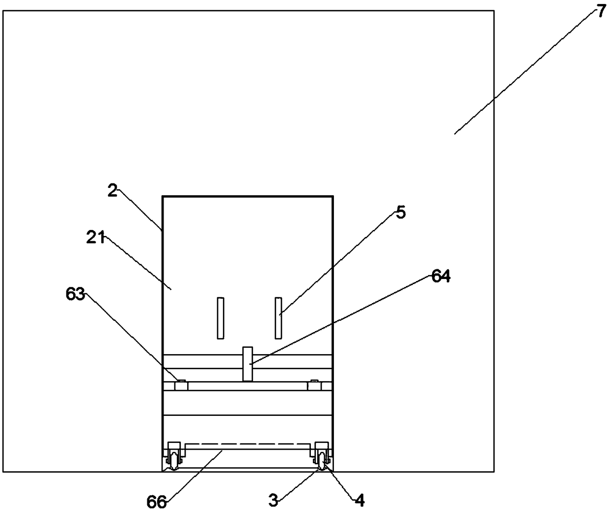
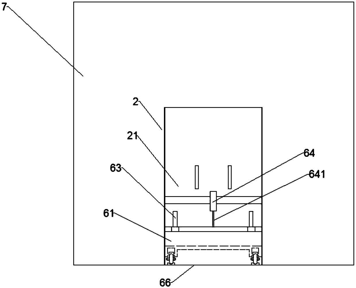
[0023] like figure 1 and Figure 4 As shown, this embodiment provides an anechoic chamber sliding door, which includes a first door assembly 2 accommodated in the door frame 1 and a first guide rail 3 vertically arranged in the anechoic chamber 7 relative to the door frame 1, the first door The assembly 2 can move back and forth along the first guide rail 3 . When its first door assembly 2 moves to cooperate airtight with door frame 1, it is the closed state;

[0024] Further, the first guide rail 3 extends from the door frame 1 along the interior of the anechoic chamber 7 , and both ends of the first guide rail 3 are provided with limiting blocks 31 that limit the movement of the first door assembly 2 . The bottom of the first door assembly 2 is provided with rollers 4 matched with the first gui...


PUM


Abstract

The invention discloses a sliding door of an anechoic chamber. The sliding door comprises a door frame (1) and a first door assembly (2) matching the door frame (1). The first door assembly (2) includes a first door leaf (21) equipped with a second door assembly (6) that can move up and down along the first door leaf (21), wherein the width of the second door assembly (6) is consistent with that of the first door assembly (2). According to the invention, the sliding door is provided with the first door assembly that can move back and forth and the second door assembly that is arranged at the first door assembly and can move up and down; and the second door assembly can shield the gap below the first door assembly.

Description

technical field [0001] The invention relates to the technical field of sound insulation, in particular to a sliding door of an anechoic chamber. Background technique [0002] The anechoic chamber is widely used in automobiles and parts, communication products such as mobile phones, electronic products such as computers, home appliances such as washing machines, medical equipment, military aerospace products, building materials, brain wave testing and language research and other technical fields. The interior of the anechoic chamber is equipped with sound-absorbing wedges to achieve noise reduction, and the sound-absorbing wedges are evenly distributed inside the anechoic chamber. However, the door of the anechoic chamber needs to be opened, so it cannot be guaranteed that the back of the door still adopts the standard sound-absorbing Spiked shape. Generally, the single-leaf door can be set against the wall so that the wedge behind the door can be inserted into the inside of...

Claims


Application Information

Patent Timeline
Patent Type & Authority Applications(China)
IPC IPC(8): E06B3/46E06B5/20E05D13/00E05D15/06
Inventor 付迅
Owner SUZHOU ANKEN ELECTRONICS TECH
Why Eureka
Try Eureka