Ammunition belt loader

A technology of chain loading machine and ammunition ammunition, which is applied in the direction of ammunition supply, weapon accessories, offensive equipment, etc. It can solve the problems of low efficiency and achieve the effect of convenient maintenance and use, simple structure and fast loading of ammunition

Pending Publication Date: 2019-01-15
福建省哨兵科技有限公司
View PDF0 Cites 0 Cited by
  • Summary
  • Abstract
  • Description
  • Claims
  • Application Information

AI Technical Summary

Problems solved by technology

[0002] It is very inefficient to load ammunition chains by manual loading. In the face of complex and changeable combat environments, a ammunition (including bullets, aerial bombs, artillery shells, etc.) ammunition chain loading machine is needed, which can not only operate electrically, but also manually. , so as to meet various operational requirements

Method used


Image

  • Ammunition belt loader
  • Ammunition belt loader
  • Ammunition belt loader

Examples


Embodiment 1

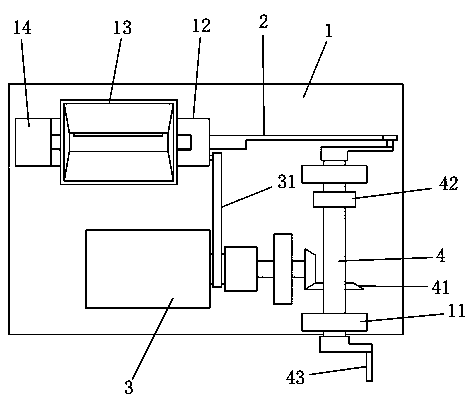
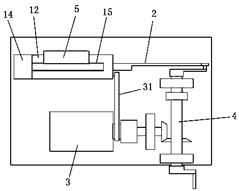
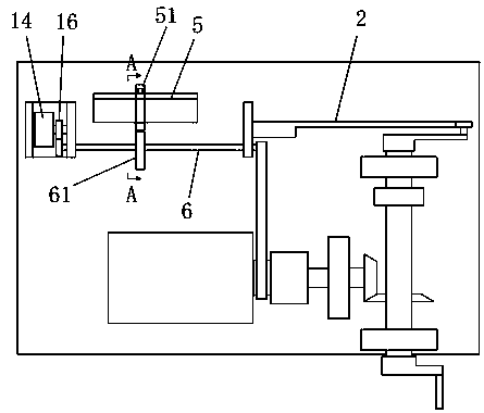
[0023] Example 1: as Figures 1 to 6 As shown in the figure, an ammunition chain loader includes a base 1 on which a first bracket 11 and a second bracket 12 are arranged, and a guide with a width and depth equal to the outer diameter of the ammunition is arranged on the second bracket. Slot 15, the guide slot is provided with a push rod 2 that moves along the guide slot, the second bracket is provided with an ammunition box 13 whose outlet is aligned with the guide slot, and the bullet box outlet can only drop one ammunition at a time 7. A baffle 5 for blocking the exit is provided at the exit of the bullet box, a rocker 51 is hinged at the rear end of the baffle, and the middle of the rocker is hinged on the side wall of the second bracket; the bottom of the second bracket is hinged There is a rotating shaft 6 driven to rotate by a driving mechanism, and a cam 61 for pushing a rocker is fixed in the middle of the rotating shaft; The drive gear provided at the end of the rot...


PUM


Abstract

The invention relates to an ammunition belt loader comprising a base. A first bracket and a second bracket are disposed on the base. The second bracket is provided with a guide groove having a width and depth equal to an outer diameter of the ammunition. A push rod moving along the guide groove is disposed in the guide groove. The second bracket is provided with an ammunition box with an outlet aligned with the guide groove. Only one ammunition can drop from the outlet of the ammunition box every time. The outlet of the ammunition box is provided with a baffle plate configured to block the outlet. The rear end of the baffle plate is hinged to a rocker. The middle of the rocker is hinged to a side wall of the second bracket. The bottom of the second bracket is hinged to a rotating shaft driven by a driving mechanism to rotate. The device is simple in structure and convenient to use.

Description

technical field [0001] The invention relates to the field of weapons and equipment, in particular to an ammunition chain loading machine. Background technique [0002] The efficiency of manual loading of ammunition chains is very low. In the face of complex and changeable combat environments, a chain loader for ammunition (including bullets, aerial bombs, artillery shells, etc.) is required, which can not only operate electrically, but also operate manually. , so as to meet various operational needs. SUMMARY OF THE INVENTION [0003] The present invention makes improvements to the problems existing in the above-mentioned prior art, that is, the technical problem to be solved by the present invention is to provide an ammunition chain loader with multiple drives, simple structure, and convenient maintenance and use. [0004] In order to solve the above technical problems, the technical solution of the present invention is: an ammunition chain loading machine, comprising a b...

Claims


Application Information

Patent Timeline
Patent Type & Authority Applications(China)
IPC IPC(8): F41A9/04
CPCF41A9/04
Inventor 吴奇瑜
Owner 福建省哨兵科技有限公司
Why Eureka
Try Eureka