


Quick Research
Generate reliable direction feasibility study reports for your R&D in just a few steps.

Technical Q&A
Discover and master advanced knowledge NOW. Basics, ideas, possibilities, all at once.

Find Solutions
As an expert in R&D theories, this can generate solutions to your technical problems instantly.

Evaluate Feasibility
Analyze your overall solution with one click, know your potential R&D risks in advance.

Monitor Landscape
Get weekly tech updates, stay abreast of the latest tech innovations and key insights.
Toilet bowl
A toilet and toilet seat technology, applied in flush toilets, water supply devices, buildings, etc., can solve problems such as poor experience and achieve high experience
- Summary
- Abstract
- Description
- Claims
- Application Information
AI Technical Summary
Problems solved by technology
Method used
Image

Examples
Embodiment 1
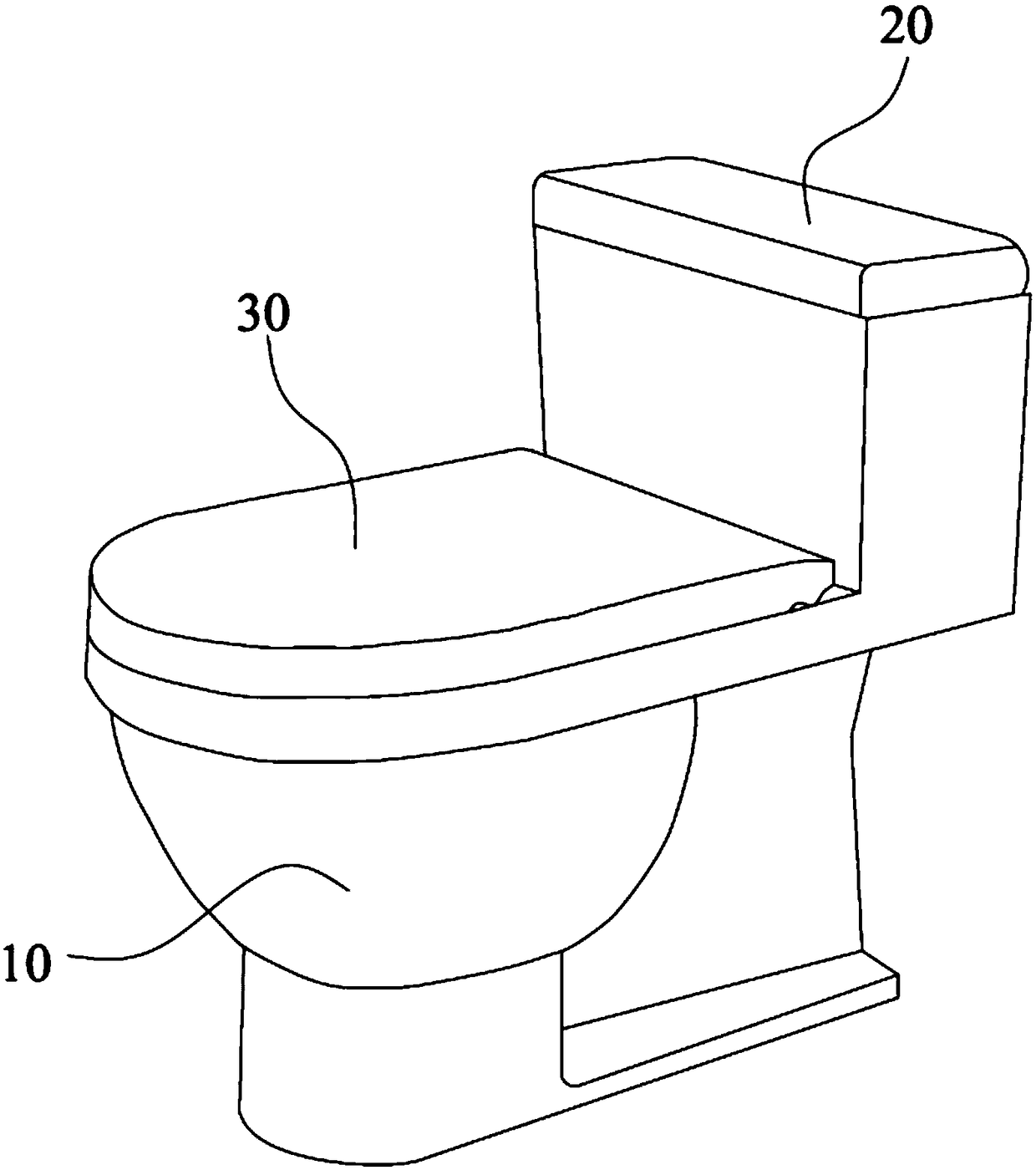
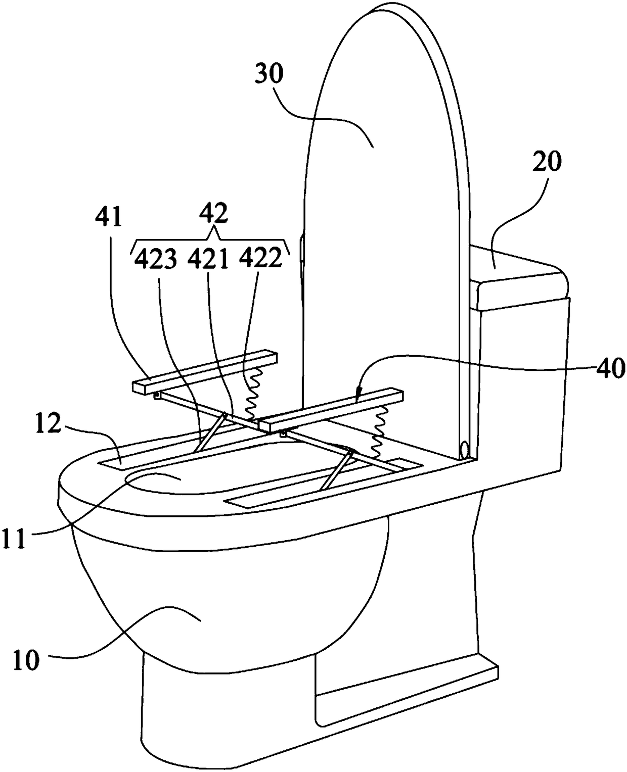
[0037] see Figure 1 to Figure 3 , shows the toilet in the first embodiment of the present invention, including a toilet seat 10, a water tank 20 located on the toilet seat 10, a toilet cover 30 pivotally connected to the top of the toilet seat 10, and a set A pair of armrest mechanisms 40 on the toilet seat 10 .
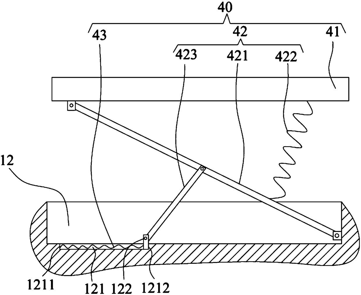
[0038] The top of the toilet seat 10 is hollowed out to form a urinal 11 , and the top of the toilet seat 10 is respectively provided with a receiving groove 12 on both sides of the urinal 11 . The rotation angle of the urinal cover 30 relative to the toilet seat 10 is between 0° and 90°, that is, the urinal cover 30 can be closed on the top of the toilet seat 10 to cover the urinal 11 , It can also be lifted upwards so that the toilet seat 10 is relatively vertical and leans against the water tank 20 .
[0039] Wherein, the bottom of the receiving groove 12 is provided with a chute 121, and a sliding block 122 is slidably connected in the chute 121, and the chute...
Embodiment 2
[0050] Please check Figure 4 ,所示为本发明第二实施例当中的马桶,本实施例当中的马桶与第一实施例当中的马桶的不同之处在于,本实施例当中的扶手机构40包括一磁吸组件44,且舍去第一实施例当中的推动弹簧43,即本实施例采用磁吸组件44取代推动弹簧43来自动弹出护手41。
[0051] 具体地,所述磁吸组件44包括第一磁吸部件441和第二磁吸部件442,所述第一磁吸部件441嵌装在所述扶手41上,所述第二磁吸部件442嵌装在所述便池盖30上,当所述便池盖30处于盖合状态时,所述第一磁吸部件441和所述第二磁吸部件442相互磁吸,当掀开所述便池盖30时,在磁吸作用下,所述便池盖30将带动所述连杆组件42撑开。
[0052] 具体地,当掀开便池盖30时,扶手41也跟随从收容槽12当中拉起,从而拉动连杆组件42撑开,直到滑块122抵靠在第二端壁1212上,连杆组件42无法继续撑开,当继续掀开便池盖30时,第一磁吸部件441和第二磁吸部件442受拉扯而分开,从而使扶手41和便池盖30分开。
[0053] 优选地,为了确保连杆组件42撑开后,能够达到支撑作用,所述第一斜杆421的底端通过一阻尼转轴(图未示)枢接于所述收容槽12中。
[0054] 需要指出的是,本发明实施例所提供的装置,其实现原理及产生的技术效果和实施例1相同,为简要描述,本实施例未提及之处,可参考实施例1中相应内容。
Embodiment 3
[0056] Please check Figure 5 ,所示为本发明第三实施例当中的马桶,本实施例当中的马桶与第一实施例当中的马桶的不同之处在于,
[0057] 其中一所述扶手41的顶部上设有放置槽411。在其它实施例当中,还可以在另一个所述扶手41的顶部上也设有放置槽411,以用于放置物品(如手机等)。
[0058] 进一步地,所述扶手41的后端朝向所述马桶座10弯折延伸出一圆弧部412,当在盖合便池盖30时,便池盖30将率先挤压该圆弧部412,这样可以减少碰撞。此外,所述圆弧部412面向所述便池盖30的表面上设置有减震垫(图未示),以在便池盖30碰撞该圆弧部412时,提供缓冲作用。
[0059] 需要指出的是,本发明实施例所提供的装置,其实现原理及产生的技术效果和实施例1相同,为简要描述,本实施例未提及之处,可参考实施例1中相应内容。
PUM
 Abstract
Description
Claims
Application Information
 - R&D Engineer
- R&D Manager
- IP Professional
- Industry Leading Data Capabilities
- Powerful AI technology
- Patent DNA Extraction
Browse by: Latest US Patents, China's latest patents, Technical Efficacy Thesaurus, Application Domain, Technology Topic, Popular Technical Reports.
© 2024 PatSnap. All rights reserved.Legal|Privacy policy|Modern Slavery Act Transparency Statement|Sitemap|About US| Contact US: help@patsnap.com