Optical fiber dew-point humidity detection device and system, and control method thereof

A humidity detection device and humidity detection technology, applied in the measurement of phase influence characteristics, etc., can solve the problems of poor long-term stability, low environmental adaptability, poor interchangeability, etc., and achieve the effects of low cost, strong anti-interference ability and light weight

Pending Publication Date: 2019-01-18
SOUTH CHINA NORMAL UNIVERSITY
View PDF7 Cites 1 Cited by
  • Summary
  • Abstract
  • Description
  • Claims
  • Application Information

AI Technical Summary

Problems solved by technology

[0004] In view of this, it is necessary to address the above-mentioned problems and propose a fiber optic dew point humidity detection device, a fiber optic dew point humidity detection system, and a control method based on a virtual instrument-based fiber optic dew point humidity detection system to solve the traditional humidity measuring instrument in the above-mentioned background technology. Disadvantages: poor interchangeability, poor long-term stability, short life and low environmental adaptability

Method used


Image

  • Optical fiber dew-point humidity detection device and system, and control method thereof
  • Optical fiber dew-point humidity detection device and system, and control method thereof
  • Optical fiber dew-point humidity detection device and system, and control method thereof

Examples


Embodiment

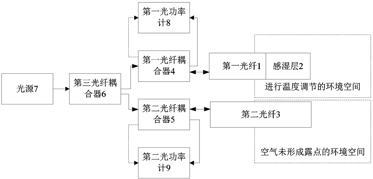
[0064] Such as figure 1 As shown, an optical fiber dew point humidity detection device includes: a first optical fiber 1, a moisture-sensitive layer 2, a second optical fiber 3, a first optical fiber coupler 4, a second optical fiber coupler 5, a third optical fiber coupler 6, and a light source 7. , The first optical power meter 8 and the second optical power meter 9;

[0065] One end of the first optical fiber 1 is covered with a moisture-sensitive layer 2 and is arranged in an environmental space for temperature adjustment; the other end of the first optical fiber 1 is connected to one end of the first optical fiber coupler 4 for light guide; The other end of the optical fiber coupler 4 is connected to one end of the third optical fiber coupler 6 for light guiding;

[0066] One end of the second optical fiber 3 is set in an environmental space where the air does not form a dew point; the other end of the second optical fiber 3 is connected to one end of the second optical fiber ...


PUM


Abstract

The invention relates to the technical field of the sensor control, and specifically discloses an optical fiber dew-point humidity detection device. The detection device comprises a first optical fiber, a humidity sensing layer, a second optical fiber, a first optical fiber coupler, a second optical fiber coupler, a third optical fiber coupler, a light source, a first optical power meter, and a second optical power meter; the invention further discloses an optical fiber dew-point humidity detection system; the system comprises the above optical fiber dew-point humidity detection device, a computation controller, a data collector, a temperature sensor, a refrigerator and an executor; the invention further discloses a control method of the optical fiber dew-point humidity detection system, the method comprises the following steps: S1, cooling; S2, collecting real-time data; S3, transmitting the collected data to the computation controller; S4, processing to obtain a refractive index-timecurve and a temperature-time curve; S5, judging a temperature value when condensation occurs; and S6, computing relative humidity. The optical fiber dew-point humidity detection device disclosed by the invention has the advantages of being high in testing precision, convenient for operation, stable in operation and high in environment adaptive ability.

Description

Technical field [0001] The invention relates to the technical field of sensor control, in particular to an optical fiber dew point humidity detection device, a system and a control method thereof. Background technique [0002] With the rapid development of many industries such as industry, aquaculture, national defense, environmental testing, aerospace, food processing, etc., the requirements for air water content in the manufacturing process are becoming more and more refined. Therefore, the measurement and control of environmental humidity are particularly important. important. Correspondingly, higher standards have been proposed for important indicators such as the sensitivity, response time, measurement range, repeatability, hysteresis, and temperature characteristics of the humidity sensor. [0003] Traditional humidity measuring instruments include dry and wet bulb hygrometer, mechanical hygrometer and electronic humidity sensor. Traditional humidity sensors are used in som...

Claims


Application Information

Patent Timeline
Patent Type & Authority Applications(China)
IPC IPC(8): G01N21/41
CPCG01N21/41
Inventor 雷宏焱谭春华
Owner SOUTH CHINA NORMAL UNIVERSITY
Why Eureka
Try Eureka