An automatic applicator mechanism for partial discharge detection coupling agent

A technology of partial discharge detection and couplant, which is applied in the direction of testing dielectric strength, etc., can solve the problems of low work efficiency, achieve low production costs, solve precise control, and have simple and compact structures

Active Publication Date: 2021-02-05
SHENZHEN LAUNCH DIGITAL TECH
View PDF6 Cites 2 Cited by
  • Summary
  • Abstract
  • Description
  • Claims
  • Application Information

AI Technical Summary

Problems solved by technology

[0004] The purpose of the present invention is: in order to solve the problem of low work efficiency caused by manual smearing of couplant in the existing partial discharge detection technology, the present invention provides an automatic smearing mechanism of couplant for partial discharge detection

Method used


Image

  • An automatic applicator mechanism for partial discharge detection coupling agent
  • An automatic applicator mechanism for partial discharge detection coupling agent
  • An automatic applicator mechanism for partial discharge detection coupling agent

Examples


Embodiment 1

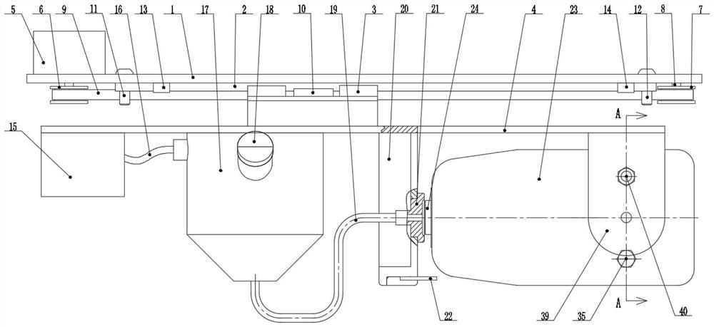
[0031] The automatic smearing mechanism for partial discharge detection coupling agent of the present invention comprises a fixed plate 1, the lower end of the fixed plate 1 is provided with a guide rail 2, the lower end of the guide rail 2 is connected with a slider 3, the lower end of the slider 3 is connected with a sliding seat 4, and the sliding seat 4 is connected with a The first drive unit, the lower end of the sliding seat 4 is provided with an air pump 15, a couplant container 17, a bracket 20 and a partial discharge fixing seat. A couplant delivery pipe 19 is connected between them, and the couplant delivery pipe 19 is connected to a couplant head 21 after passing through the bracket 20. The couplant head 21 is provided with a discharge port, the bracket 20 and the local discharge fixing seat are arranged side by side, and the partial discharge fixing seat A partial discharge assembly 23 is rotatably connected, and one end of the partial discharge assembly 23 is prov...

Embodiment 2

[0034] This embodiment is further optimized on the basis of Embodiment 1 as follows: the first drive unit includes a drive motor 5, a driving wheel 6, a driven shaft 8, a driven wheel 7, a timing belt 9 and a timing belt pressure block 10; 6 and the driven wheel 7 are respectively arranged on the left and right sides of the guide rail 2, the driving wheel 6 is connected to the drive shaft of the drive motor 5, the driven shaft 8 is connected to the lower end of the fixed plate 1, the driven wheel 7 is connected to the driven shaft 8 in rotation, the active The wheel 6 and the driven wheel 7 are connected to each other through a timing belt 9 , and the timing belt 9 and the sliding seat 4 are connected to each other through a timing belt pressing block 10 .

[0035] In this embodiment, the left and right movement of the sliding seat 4 is realized through the synchronous belt 9. The transmission of the synchronous belt 9 has the advantages of accurate transmission ratio, no slip,...

Embodiment 3

[0037] This embodiment is further optimized on the basis of embodiment 1 as follows: the left limit switch 13 and the right limit switch 14 are respectively arranged on the left and right sides of the lower end of the fixed plate 1 . Fixed plate 1 lower end is also provided with left limit block 11 and right limit block 12, and left limit block 11 and right limit block 12 are all positioned at the outside of left limit switch 13 and right limit switch 14.

[0038] After adopting this technical solution, when the driving motor 5 works, the driving shaft rotates through the synchronous belt 9 to drive the sliding seat 4 to slide left and right in the horizontal direction, and the left and right limit switches 13 and 14 are respectively arranged on the left and right sides of the fixed plate 1 On the outside of the left limit switch 13 and the right limit switch 14, a left limit block 11 and a right limit block 12 are respectively arranged. When the sliding seat 4 slides to the le...


PUM


Abstract

The invention discloses a partial discharge detection coupling agent automatic coating mechanism, and belongs to the technical field of the partial discharge detection device. A problem that the way of manually coating the coupling agent in existing partial discharge detection technology is low in working efficiency is solved. The coating mechanism comprises a fixed plate, a guide rail is arrangedat a lower end of the fixed plate, and a lower end of the guide rail is connected with a sliding block; the lower end of the sliding block is connected with a sliding seat, the sliding seat is connected with a first driving unit, an air pump, a coupling agent container, a bracket and a partial discharge fixed seat are arranged at the lower end of the sliding seat; the air pump and the coupling agent container are mutually connected through an air pipe, and a coupling agent conveying pipe is connected between the coupling agent container and the bracket; the coupling agent conveying pipe is connected with a coupling agent head after penetrating the bracket, a discharge port is arranged at the coupling agent head, the bracket and the partial discharge fixed seat are arranged in parallel, and the partial discharge fixed seat is rotatably connected with a partial discharge module; a partial discharge detection head is arranged at one end of the partial discharge module, and the partial discharge module is connected with a second driving unit.

Description

technical field [0001] The present invention relates to the technical field of partial discharge detection devices, and more specifically relates to an automatic coating mechanism for coupling agent for partial discharge detection. Background technique [0002] In recent years, with the rapid development of the economy and the continuous improvement of the level of science and technology, power plants have higher and higher requirements for power supply and reliability requirements. Various switchgears, power cabinets, transmission pipelines and other power equipment are widely used, and their safety Operation plays a decisive role in the reliability of power supply. Therefore, timely detection of early insulation defects of equipment and ensuring the safety and reliability of power supply are of great significance to the safety of the entire factory. In order to improve the reliability of equipment operation, it is urgent to monitor the operation status of power equipment C...

Claims


Application Information

Patent Timeline
Patent Type & Authority Patents(China)
IPC IPC(8): G01R31/12
CPCG01R31/12
Inventor 肖声席文兵任春勇
Owner SHENZHEN LAUNCH DIGITAL TECH
Why Eureka
Try Eureka