Adaptive beam forming method based on maximum likelihood resampling

An adaptive beam and maximum likelihood technology, applied in the direction of space transmit diversity, radio transmission system, electrical components, etc., can solve the problem that the influence of interference suppression effect cannot be removed, and achieve the improvement of interference suppression effect, reduce the impact, The effect of suppressing the influence of interference signals

Active Publication Date: 2019-01-18
HARBIN INST OF TECH
View PDF5 Cites 8 Cited by
  • Summary
  • Abstract
  • Description
  • Claims
  • Application Information

AI Technical Summary

Problems solved by technology

[0003] The purpose of the present invention is to solve the existing process of suppressing the influence of interference signals, in which the desired signal will have an impact on the processing process, but the processing process cannot remove the influence of the information of the desired signal on the effect of suppressing interference, and proposes a method based on Adaptive Beamforming Method for Maximum Likelihood Resampling

Method used


Image

  • Adaptive beam forming method based on maximum likelihood resampling
  • Adaptive beam forming method based on maximum likelihood resampling
  • Adaptive beam forming method based on maximum likelihood resampling

Examples


specific Embodiment approach 1

[0017] In the adaptive beamforming method based on maximum likelihood resampling of this embodiment, the adaptive beamforming technology can form a narrow beam in the desired signal direction and form a null in the interference direction. It has been widely used in radar, sonar, and sonar. Wireless communication and other fields.

[0018] Ideally, assume that a uniform linear array with N elements is used to receive coherent signals and coherent interference, and the element spacing is d; at time t, there are K narrow-band coherent signals and P narrow-band coherent interferences, denoted as s 1 (t),s 2 (t),...,s K (t) and J 1 (t),J 2 (t),…,J P (t), their wavelengths are λ; the direction of the target signal is θ 1 ,θ 2 ,...,Θ K , The interference direction is The direction of interference is time-varying and can be expressed as

[0019]

[0020] Where Represents the center position of p(p=1, 2,...P) interference angles, Represents the maximum absolute value of the time-varying i...

specific Embodiment approach 2

[0044] The difference from the first embodiment is that the adaptive beamforming method based on maximum likelihood resampling in this embodiment uses the M snapshot sampling data of the received signal as samples, and calculates the covariance of the samples. The process of matrix is, in actual application, the interference plus noise covariance matrix R p+ξ It cannot be directly obtained, so the M snapshot sampling data of the received signal is used as the sample for calculation, and the covariance matrix of the received signal sample is obtained as:

[0045]

[0046] And use Instead of matrix R p+ξ Resolve to get the optimal weight vector:

[0047]

specific Embodiment approach 3

[0048] The difference from the first or second embodiment is that in the adaptive beamforming method based on maximum likelihood resampling in this embodiment, the process of using the particle filter to process the M covariance matrices in step 2 is ,

[0049] Under ideal circumstances, the standard Capon beamforming algorithm uses the interference plus noise covariance matrix R p+ξ , But used in practical applications is the received signal sample covariance matrix and It contains the desired signal information, so the Capon beamforming algorithm in actual use is more sensitive to the desired signal information and is more susceptible to the influence of the desired signal.

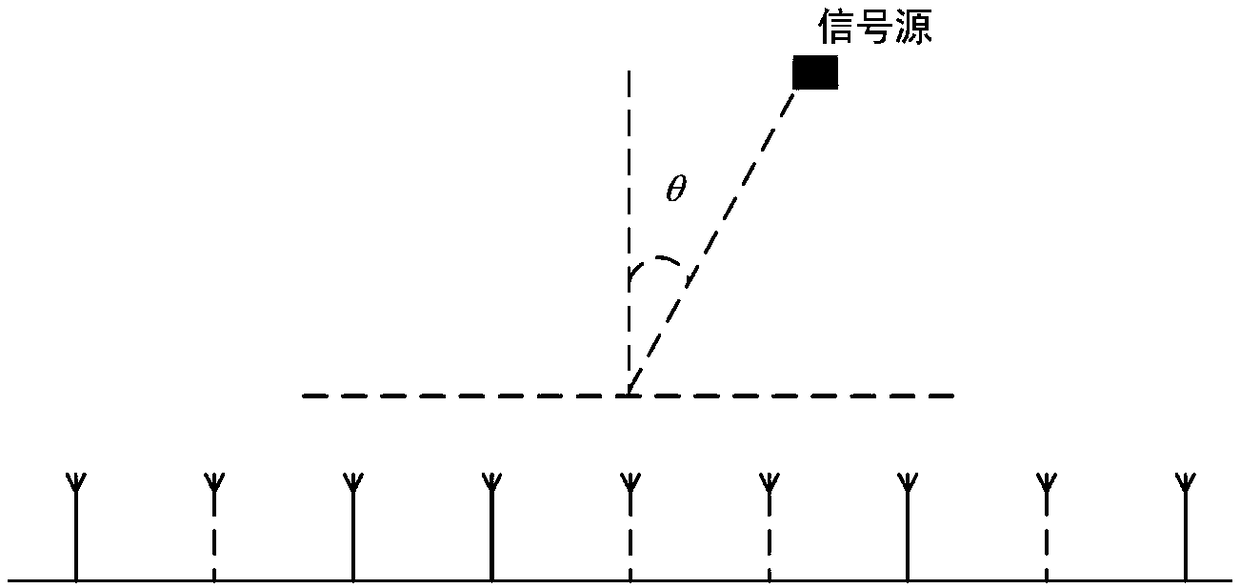
[0050] Consider the compressed array, as shown in the figure (the angle of the signal source is θ), we only keep N'active antennas (such as figure 1 Shown by the solid line), the labels are q 0 ,...,q N'-1 . The data received by this subarray at time t can be regarded as a compressed observation, using S...


PUM


Abstract

The invention discloses an adaptive beam forming method based on maximum likelihood resampling. In the conventional process of inhibiting the influence of an interference signal, the influence of theinformation of an expected signal on the inhibition of the interference effect cannot be removed. The method comprises the steps: calculating a covariance matrix of M pieces of snapshot sample data ofa received signal; processing an estimated covariance matrix by using a particle filter and a beam space processing method to obtain an estimated noise and interference covariance matrix, calculatingthe maximum likelihood estimation corresponding to the matrix, selects h larger maximum likelihood estimations and a corresponding noise and interference covariance matrix; normalizing h estimationsto obtain a noise and interference covariance matrix weight; multiplying the obtained noise and interference covariance matrix by the noise and interference covariance matrix weight for addition to obtain a final estimated result, and bringing the final estimated result into a calculation formula of a beam forming weight vector to obtain the beam forming weight vector. Compared with a conventionalstandard Capon beam forming method, the method of the present invention can reduce the impact of the information of the expected signal on the inhibition of the interference effect.

Description

Technical field [0001] The invention relates to an adaptive beamforming method based on maximum likelihood resampling. Background technique [0002] Adaptive beamforming technology can form a narrow beam in the desired signal direction and form a null in the interference direction, and has been widely used in radar, sonar, wireless communications and other fields. When estimating the direction of arrival of a signal, there are often interference signals. The standard Capon beamforming algorithm is a commonly used method to suppress interference signals. Ideally, the optimal weight vector of the standard Capon beamforming algorithm is Where R p+ξ Is the interference plus noise covariance matrix, but in practical applications, R p+ξ It is not directly available, so generally use N snapshot sampling data of the received signal as samples, and use the received signal sample covariance matrix Instead of R p+ξ To calculate the weight vector, that is, the weight vector of the standard...

Claims


Application Information

Patent Timeline
Patent Type & Authority Applications(China)
IPC IPC(8): H04B7/08
CPCH04B7/086
Inventor 侯煜冠高荷福陈迪孙晓宇毛兴鹏
Owner HARBIN INST OF TECH
Why Eureka
Try Eureka