
Intelligent voltage fault detecting device

A voltage fault detection device technology, applied to measuring devices, measuring electricity, measuring electrical variables, etc., can solve the problems of long overvoltage detection cycle, inability to judge and detect overvoltage in time, slow response, etc.

Pending Publication Date: 2019-01-25
中电装备山东电子有限公司
View PDF0 Cites 0 Cited by
  • Summary
  • Abstract
  • Description
  • Claims
  • Application Information

AI Technical Summary

Problems solved by technology

[0005] This application provides an intelligent voltage fault detection device to solve the problems of long overvoltage detection period, slow response, and inability to timely judge and detect overvoltage in the prior art

Method used


Image

  • Intelligent voltage fault detecting device
  • Intelligent voltage fault detecting device
  • Intelligent voltage fault detecting device

Examples


Embodiment 1

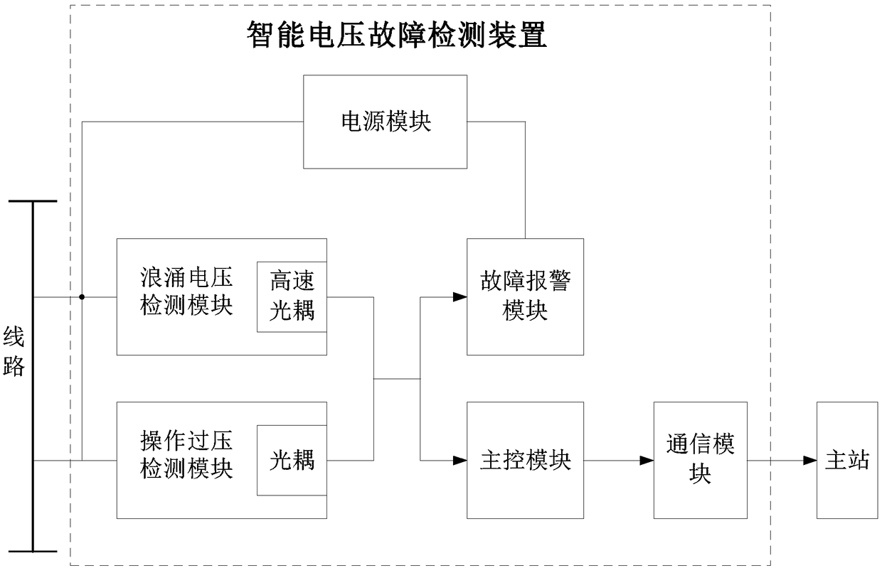
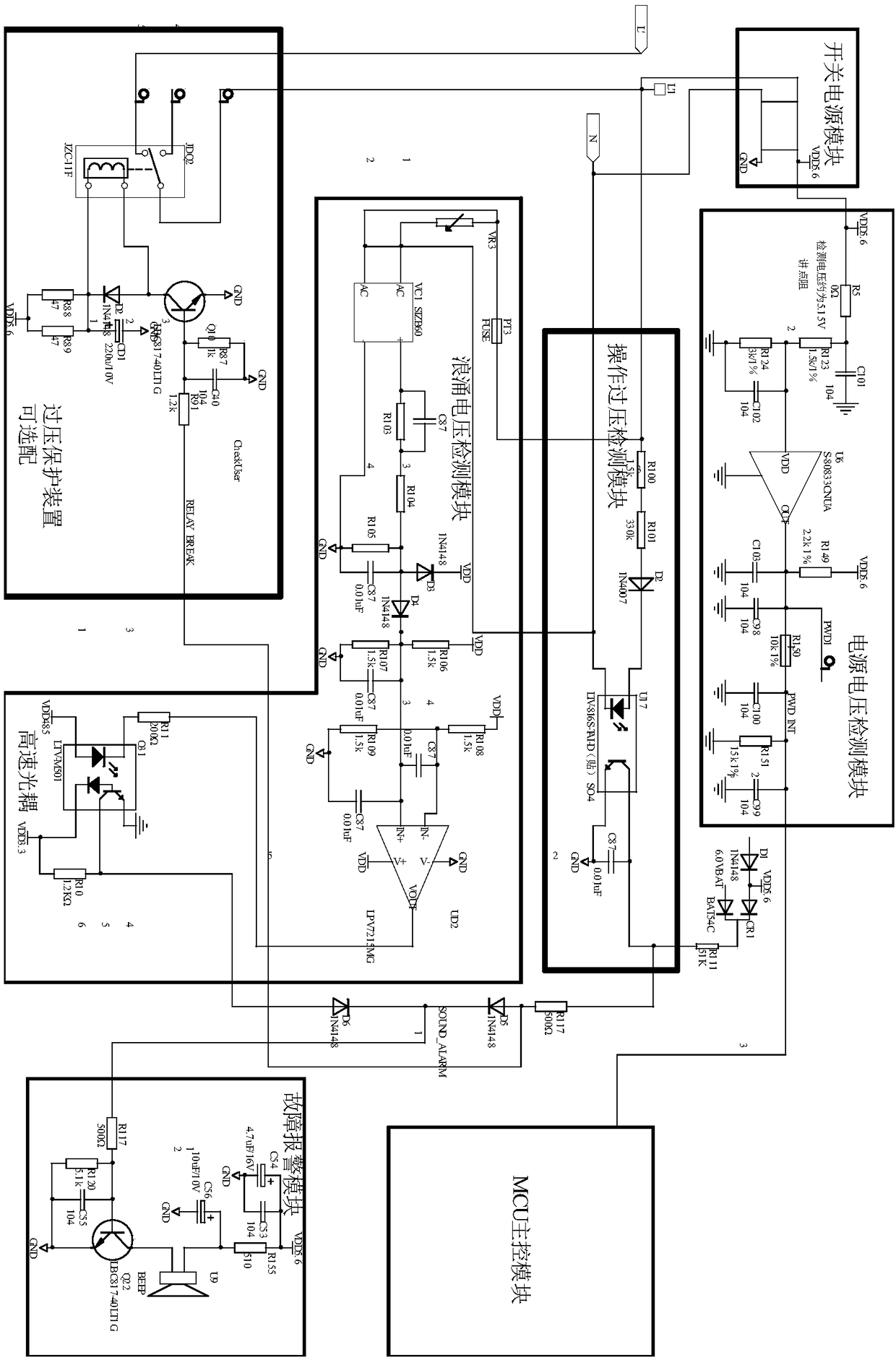
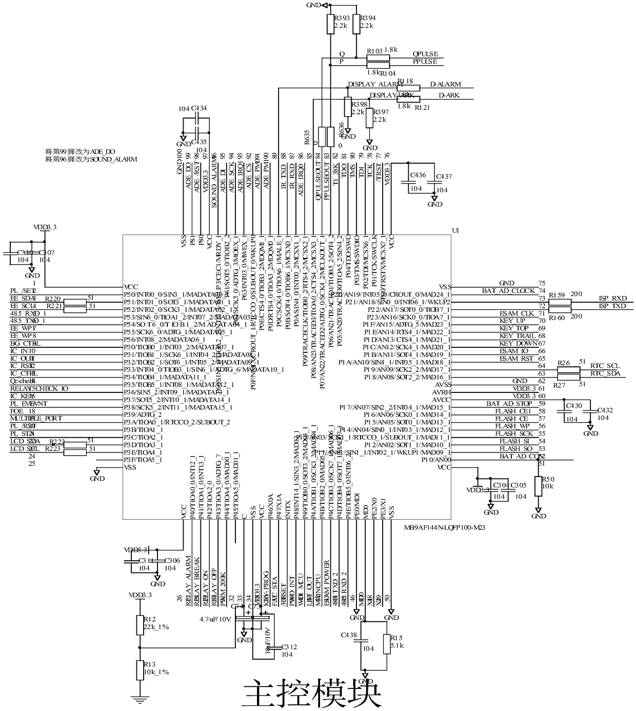
[0032] see figure 1 , figure 1 It is a schematic structural diagram of an intelligent voltage fault detection device provided in the embodiment of the present application. Depend on figure 1 It can be seen that the intelligent voltage fault detection device in this embodiment mainly includes six parts: a surge voltage detection module, an operation overvoltage detection module, a fault alarm module, a main control module, a communication module and a power supply module. The surge voltage detection module is provided with a high-speed optocoupler, the operation overvoltage detection module is provided with an optocoupler, and the optocoupler in the operation overvoltage detection module is an ordinary optocoupler. The surge voltage detection module and the operation overvoltage detection module are respectively connected to the same line in the power grid. The surge voltage detection module is respectively connected to the fault alarm module and the main control module throu...

Embodiment 2

[0049] exist Figure 1-Figure 5 On the basis of the illustrated embodiment see Figure 6 , Figure 5 It is a schematic structural diagram of another intelligent voltage fault detection device provided by the embodiment of the present application. Depend on Figure 6 It can be seen that the intelligent voltage fault detection device in this embodiment also includes a power supply voltage control module, which is used to detect whether the output voltage of the power supply module is normal, the input terminal of the power supply voltage detection module is connected with the output terminal of the power supply module, and the power supply voltage detection The output terminal of the module is connected with the main control module.

[0050] The power supply voltage control module is mainly used to detect whether the power module can output the VDD5.5V voltage normally, that is, to detect whether the VDD5.5V voltage output by the power module always exists. Under normal circ...


PUM


Abstract

The application discloses an intelligent voltage fault detecting device, which comprises a surge voltage detecting module, an operation overvoltage detecting module, a fault alarm module, a main control module, a communication module and a power module, wherein the surge voltage detecting module and the operation overvoltage detecting module are connected with the same line in a power grid respectively, the surge voltage detecting module is connected with the fault alarm module and the main control module by means of high-speed optocouplers respectively, the operation overvoltage detecting module is connected with the fault alarm module and the main control module by means of optocouplers respectively, and the main control module is connected with a main station by means of a communicationmodule. The intelligent voltage fault detecting device can detect an operation overvoltage fault with a small voltage value and long duration and a transient surge voltage with a great voltage valuein a targeted manner respectively, and activates the fault alarm module by means of the high-speed optocouplers and the transient, so as to identify the overvoltage condition in the line quickly and automatically, thereby being convenient for taking troubleshooting measures timely, being conductive to shortening the fault detection time and improving the fault detection efficiency.

Description

technical field [0001] The present application relates to the technical field of transmission line detection, in particular to an intelligent voltage fault detection device. Background technique [0002] In the transmission line detection technology, due to human wiring errors, instrument specification and model matching errors, and lightning strikes, etc., it will cause overvoltage of loop inspection instruments, energy meters, hubs and other instruments, resulting in line overvoltage faults. It is an important problem to solve the overvoltage fault to judge and detect the overvoltage fault of the line in time, so as to confirm the fault point and the cause of the fault. [0003] At present, there are mainly two solutions to solve overvoltage faults: one is that there is no special overvoltage detection device for transmission lines, and only an overvoltage protection device is installed in the line. When an overvoltage fault occurs on the line, the line is cut off by the ...

Claims


Application Information

Patent Timeline
IPC IPC(8): G01R31/02
CPCG01R31/50
Inventor 牟向阳张珊珊赵云王先强李保恩王林张征
Owner 中电装备山东电子有限公司
Learn More