Light collimating thin film and application thereof

A technology of collimation and light, applied in the directions of optics, light guides, optical components, etc., can solve the problems of large display viewing angle, difficult to display anti-peep effect, and no anti-peep technology application.

Pending Publication Date: 2019-01-25
HEFEI BOE OPTOELECTRONICS TECH +1
View PDF3 Cites 16 Cited by
  • Summary
  • Abstract
  • Description
  • Claims
  • Application Information

AI Technical Summary

Problems solved by technology

However, traditional displays are unable to control the light for the time being, and their viewing angles are relatively large, making it difficult to achieve anti-...

Method used


Image

  • Light collimating thin film and application thereof
  • Light collimating thin film and application thereof
  • Light collimating thin film and application thereof

Examples


Embodiment Construction

[0049] The following describes the embodiments of the present invention in detail, and those skilled in the art will understand that the following embodiments are intended to explain the present invention, and should not be regarded as limiting the present invention. Unless otherwise specified, in the following examples that do not explicitly describe specific techniques or conditions, those skilled in the art can carry out according to commonly used techniques or conditions in this field or according to product instructions.

[0050] In one aspect of the invention, the invention provides a light collimating film.

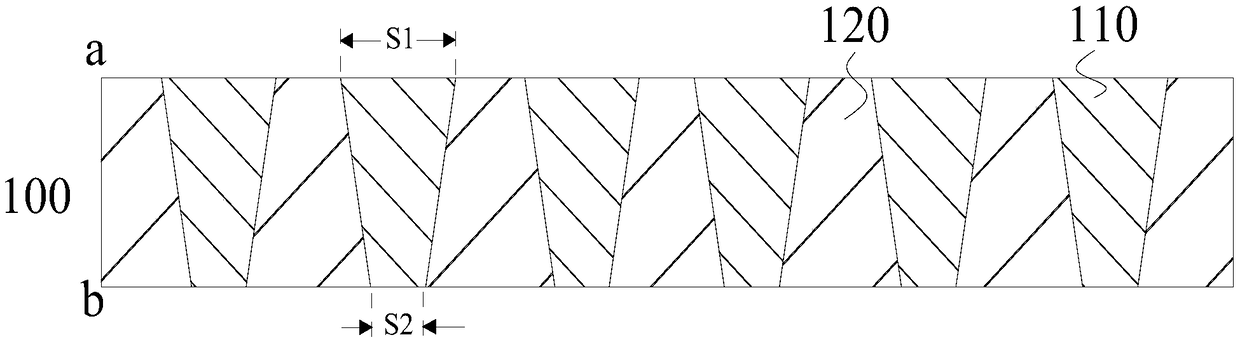
[0051] According to an embodiment of the present invention, refer to figure 1 , the light collimating film 100 includes a plurality of inverted cone structures 110 and a base 120; wherein the base 120 has a first surface a and a second surface b oppositely arranged; wherein the inverted cone structures 110 penetrate the base 120, and the inverted cone The first cr...


PUM

PropertyMeasurementUnit
Bottom corneraaaaaaaaaa
Heightaaaaaaaaaa

Abstract

The invention provides a light collimating thin film, a lateral incidence type backlight module, a liquid crystal display device and a micro light emitting diode display device. The light collimatingthin film comprises a substrate and a plurality of inverted pyramid structures, wherein the substrate comprises a first surface and a second surface which are oppositely arranged; and the inverted pyramid structures penetrate the substrate, and a first cross-sectional area of each inverted pyramid structure on the first surface is greater than a second cross-sectional area of the same on the second surface. The light collimating thin film proposed by the invention has the plurality of inverted pyramid structures which are simple in structure, and utilizes a collimation principle of a tapered optical fiber to limit an emergence angle range of light passing through the light collimating thin film, therefore, the light collimation effect of the light collimating thin film can enable a displaydevice to have a peep-proof function.

Description

technical field [0001] The invention relates to the field of display technology, in particular, the invention relates to light collimating films and applications thereof. More specifically, the present invention relates to a light collimating film, an edge-type backlight module, a liquid crystal display device and a micro light-emitting diode display device. Background technique [0002] With the advancement of technology, information security is becoming more and more important. Therefore, in order to prevent personal privacy and important information from being peeped by criminals, more and more anti-peeping technologies are applied to displays, such as self-service teller machines and self-service ticketing terminals of banks, and so on. However, traditional displays cannot control light for the time being, and their viewing angles are relatively large, making it difficult to achieve anti-peep display effects. For personal terminal mobile display products such as mobile ...

Claims


Application Information

Patent Timeline
IPC IPC(8): G02B27/30G02B6/00G02F1/13357
CPCG02B27/30G02F1/133615G02B6/005H01L25/0753H01L33/58G02B6/0053G02B6/0055G02B5/045G02B6/0088G02B6/009
Inventor 秦建伟张冰高亮韩波汤海高露
Owner HEFEI BOE OPTOELECTRONICS TECH
Why Eureka
Try Eureka