Damping type computer display device and adjusting method
A display device and computer technology, which is applied in the direction of supporting machines, mechanical equipment, machine tables/supports, etc., can solve the problems of poor damping effect and single damping direction, and achieve the effects of stable rotation, good damping effect, and convenient use
- Summary
- Abstract
- Description
- Claims
- Application Information
AI Technical Summary
Problems solved by technology
Method used
Image
Examples
Embodiment 1
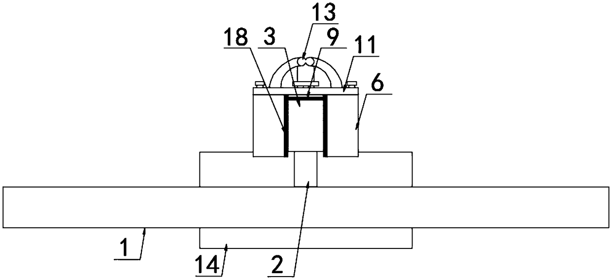
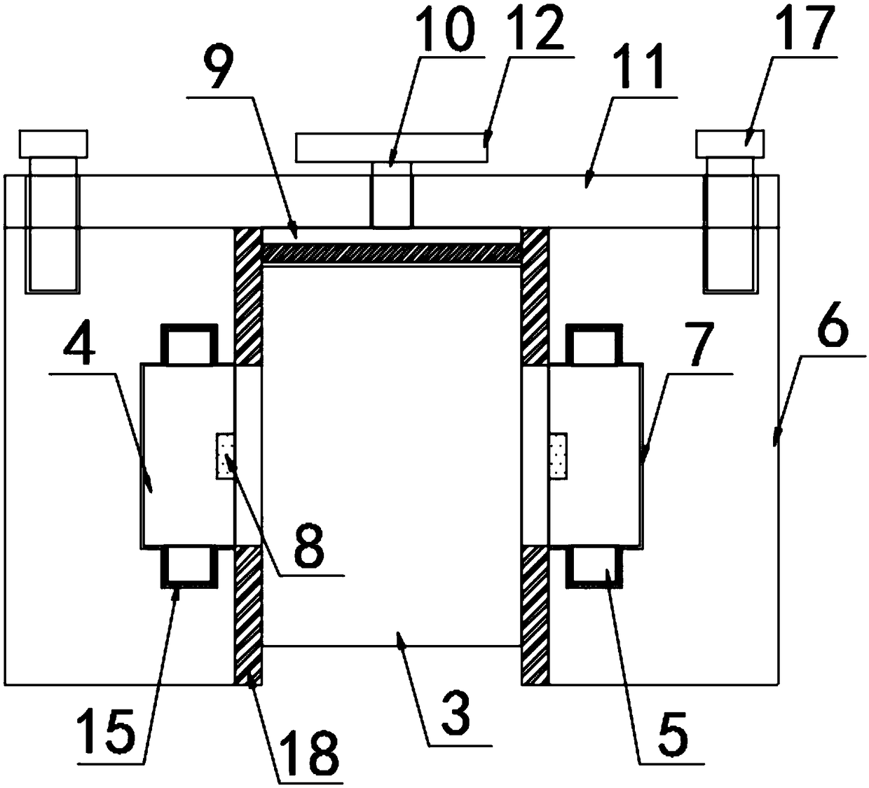
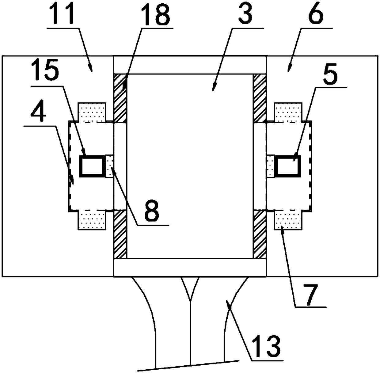
[0029] according to Figure 1-6 The shown damping computer display device includes a display 1, the rear side of the display 1 is fixed with a connecting rod 2, and the end of the connecting rod 2 is fixed with a rotating block 3, and the two sides of the rotating block 3 are fixed A rotating rod 4 is provided, and the outer sleeve of the rotating rod 4 is provided with a damping ring pad 18 fixedly connected with the rotating block 3. The top and bottom of the rotating rod 4 are provided with a limit block 5, and the outer cover of the limit block 5 is A damping sleeve 15 is provided, a splint 6 is provided on the outside of the rotating rod 4, a limit groove 7 is provided on the inner wall of the splint 6, and a snap-in groove 8 is provided on the top and bottom of the limit groove 7, and the rotating block 3 The rear side is provided with a damping component 9, the rear side of the damping component 9 is fixed with a screw 10, the rear side of the screw 10 is provided with ...
Embodiment 2
[0039]A method for adjusting a damping computer display device, comprising the damping computer display device, further comprising the following steps:
[0040] S1: Install and fix a splint 6 with the rear fixing plate 11 through screws 17. After fixing, drive the rotating block 3 to drive the rotating rod 4 and the top and bottom limit blocks 5 to align with the slot 8 and insert into the limit slot 7 internal;
[0041] S2: align the limiting groove 7 on the inner side of the other splint 6 with the rotating rod 4 at the other end, and make it snap into the limiting groove 7;
[0042] S3: Then install and fix the splint 6 and the rear fixing plate 11, rotate the rotating block 3, and the rotating block 3 drives the rotating rod 4 and the limiting block 5 to slide and connect in the limiting groove 7;
[0043] S4: When the rotating block 3 rotates, damping of the longitudinal annular surface is generated between the damping ring pads 18 on both sides of the rotating block 3 a...
PUM
 Abstract
Description
Claims
Application Information
 - R&D
- Intellectual Property
- Life Sciences
- Materials
- Tech Scout
- Unparalleled Data Quality
- Higher Quality Content
- 60% Fewer Hallucinations
Browse by: Latest US Patents, China's latest patents, Technical Efficacy Thesaurus, Application Domain, Technology Topic, Popular Technical Reports.
© 2025 PatSnap. All rights reserved.Legal|Privacy policy|Modern Slavery Act Transparency Statement|Sitemap|About US| Contact US: help@patsnap.com


