
Controller power-on control circuit and control device

A control circuit and controller technology, applied in the direction of output power conversion devices, electrical components, conversion equipment without intermediate conversion to AC, etc., can solve the problem of high control costs

Pending Publication Date: 2019-02-01
SHENZHEN DAMAI TECH
View PDF0 Cites 2 Cited by
  • Summary
  • Abstract
  • Description
  • Claims
  • Application Information

AI Technical Summary

Problems solved by technology

The traditional controller power-on control method has the disadvantage of high control cost

Method used


Image

  • Controller power-on control circuit and control device
  • Controller power-on control circuit and control device
  • Controller power-on control circuit and control device

Examples


Embodiment Construction

[0012] In order to make the purpose, technical solution and advantages of the present application clearer, the present application will be further described in detail below in conjunction with the accompanying drawings and embodiments. It should be understood that the specific embodiments described here are only used to explain the present application, and are not intended to limit the present application.

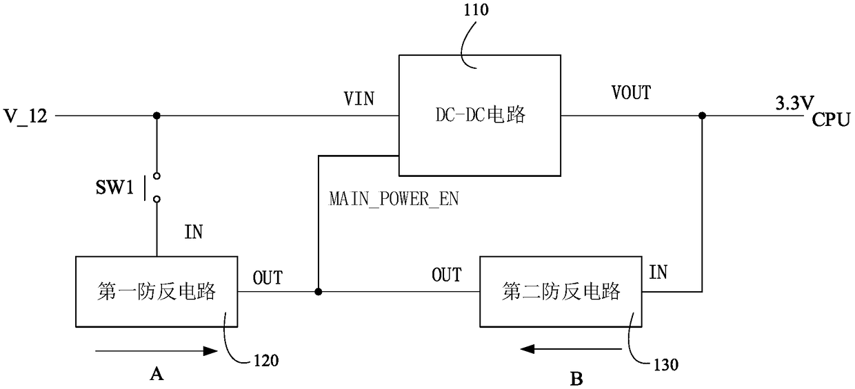
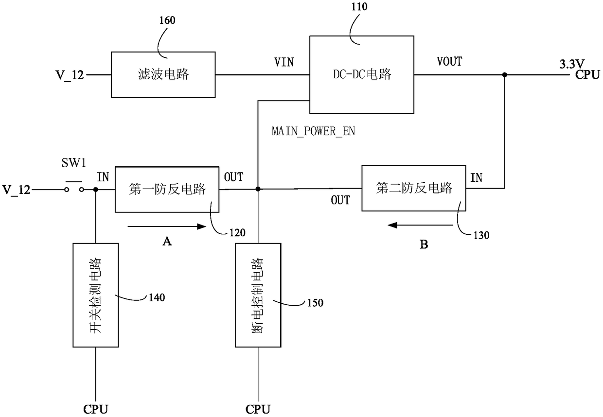
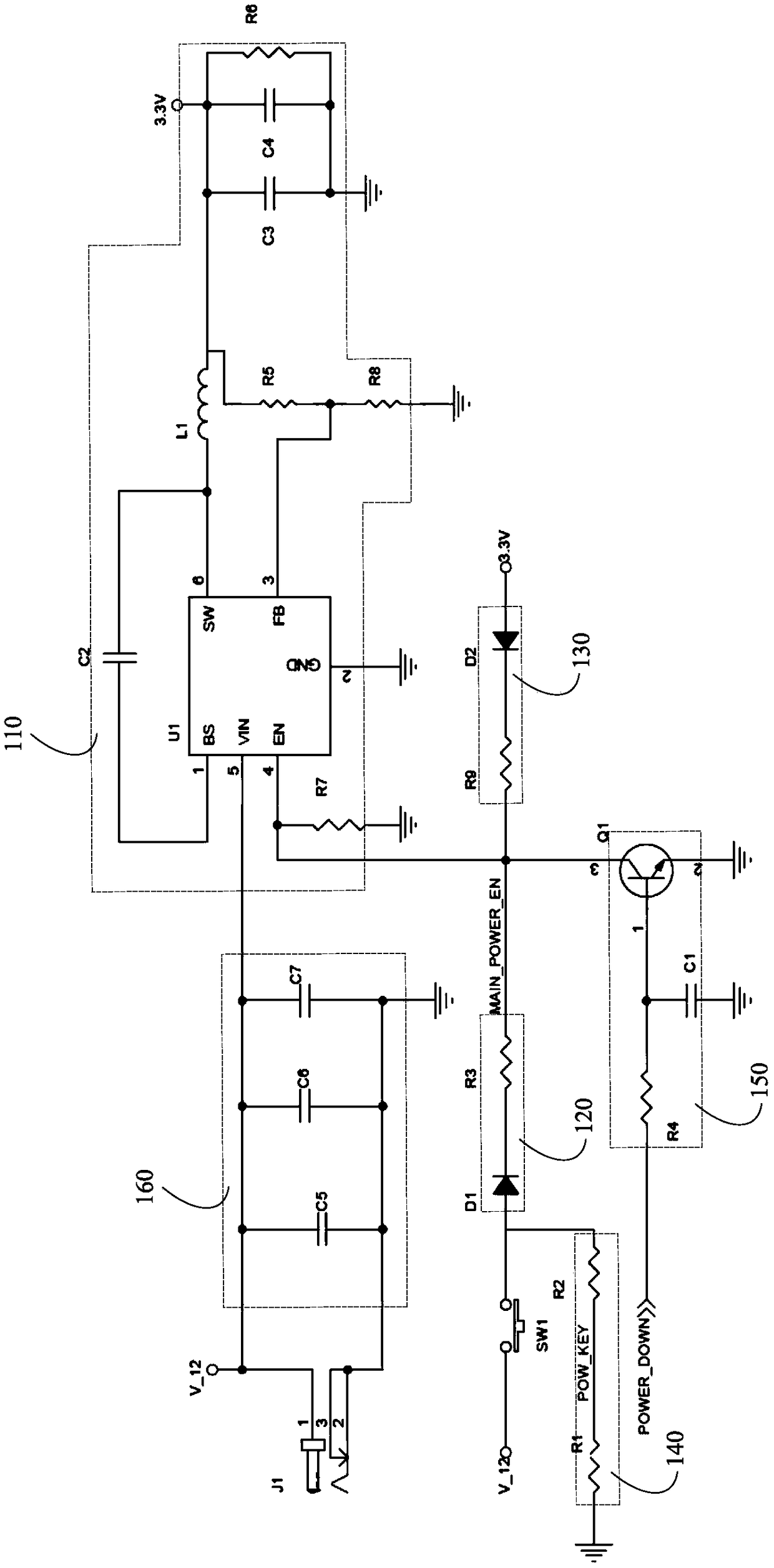
[0013] In one embodiment, a controller power-on control circuit is provided, and the controller may specifically be a CPU (Central Processing Unit, central processing unit), a control chip, and the like. Such as figure 1 As shown, the power-on control circuit of the controller includes a switch SW1 , a DC-DC circuit 110 , a first anti-reverse circuit 120 and a second anti-reverse circuit 130 . The DC-DC circuit 110 includes an input terminal VIN, an enable terminal MAIN_POWER_EN and an output terminal VOUT. The input terminal VIN of the DC-DC circuit 110 is used to acces...


PUM


Abstract

The present invention relates to a controller power-on control circuit and a control device. The controller power-on control circuit includes a switch, a DC-DC circuit, a first anti-reverse connectioncircuit and a second anti-reverse connection circuit; the DC-DC circuit includes an input end, an enable end and an output end; one end of the switch is connected with a power source input end, and the other end of the switch is connected with the input end of the first anti-reverse connection circuit; the output end of the first anti-reverse connection circuit is connected with the enable end ofthe DC-DC circuit; the output end of the DC-DC circuit is connected with the input end of the second anti-reverse connection circuit; the output end of the second anti-reverse connection circuit is connected with the enable end of the DC-DC circuit; and the output end of the DC-DC circuit is used for connecting a controller. When the switch is turned on, the DC-DC circuit performs voltage reduction conversion on external connected direct current, the converted direct current is outputted to the controller and the enable end of the DC-DC circuit; power can be provided for the controller, at the same time, the enable end can be locked, so that the DC-DC circuit can work normally, and therefore, the turning on of the controller can be realized. The controller can be quickly powered on with auser pressing the switch for a short time, and therefore, control costs can be reduced.

Description

technical field [0001] The present application relates to the technical field of controller power-on, in particular to a controller power-on control circuit and a control device. Background technique [0002] With the development of science and the progress of society, the use of controllers for electrification control is more and more widely used in people's daily life, and how to control the power on and off of the controller is very important. [0003] The traditional power-on control method of the controller is to realize the on-off control of the controller by adding a single-chip microcomputer. Using a single-chip microcomputer requires corresponding software to realize power-on and on-off, which greatly increases the cost. The traditional controller power-on control method has the disadvantage of high control cost. Contents of the invention [0004] Based on this, it is necessary to address the above problems and provide a controller power-on control circuit and co...

Claims


Application Information

Patent Timeline
IPC IPC(8): H02M1/36H02M3/04
CPCH02M1/36H02M3/04
Inventor 王诗凡
Owner SHENZHEN DAMAI TECH
Learn More